

Blog 1: Gears

Updated: Nov 14, 2024
Hi guys, welcome back to my blog after a long time from my last blogging module! Check out the goals that I want to achieve upon completing this Chemical Product Design and Development module and I hope you guys are learning the content along with me by reading through my blog. Although my blog might not be the most interesting one, I will document my learning process and explain the knowledge that I have learnt for every single practical session.
Without further ado, let's get STARTED.....

Have you ever wondered what makes the wheels in a clock tick, or how a simple hand-squeezed fan creates a cool breeze with just a squeeze?
Behind these everyday mechanisms lies a fascinating science of gears, where the interplay of force, speed, and torque brings machines to life. In this post, I’ll dive into the world of gears, exploring their mechanics and showing how our team used them in a hands-on project to lift a water bottle.
Whether you’re curious about design principles or looking to tackle your own DIY gear project, join me as we unravel the powerful potential hidden within each turn of a gear!
What is Gear?
Before I show you the interesting gear project that I did, I would like to share some basic knowledge about the GEAR.
This short video explains about the key concepts in gear system. Fret not, I will explain further about the GEARSSS if you cannot fully understand the video or you feel that the video provided limited information.
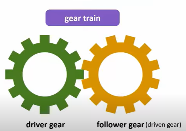
First of all, a gear is a wheel with TEETH.
TEETH?
TEETH?
TEETH?
When 2 gears fit together, it is called a gear train. They will turn in opposite direction.
Gear module
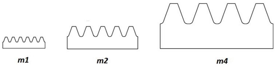
refers to the size of the gear teeth. The unit for module is mm.
The larger a module number, the larger is the size of the teeth. Gears that mesh together are having the same module.
Pitch Circular Diameter (PCD)
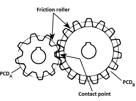
The imaginary circle that passes through the contact point between 2 meshing gears. It represents the diameters of two friction rollers in contact and moves at the same linear velocity.
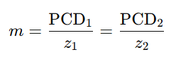
Relationship between gear module (m), pitch circular diameter (PCD) and number of teeth (z)
The larger the module(m), the lesser the number of teeth(z), the smaller the PCD. It is shown by the formula below.
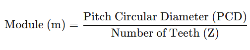
That said, recall what gear module is, gears that mesh together are having the same module.
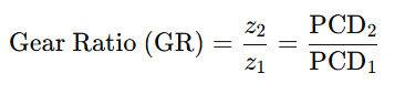
Gear ratio
Therefore, gear ratio can be determined by number of teeth, torque and speed as below.
Method 1:
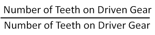
Example:
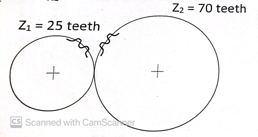
70/25=2.8
Method 2:
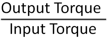
Example:
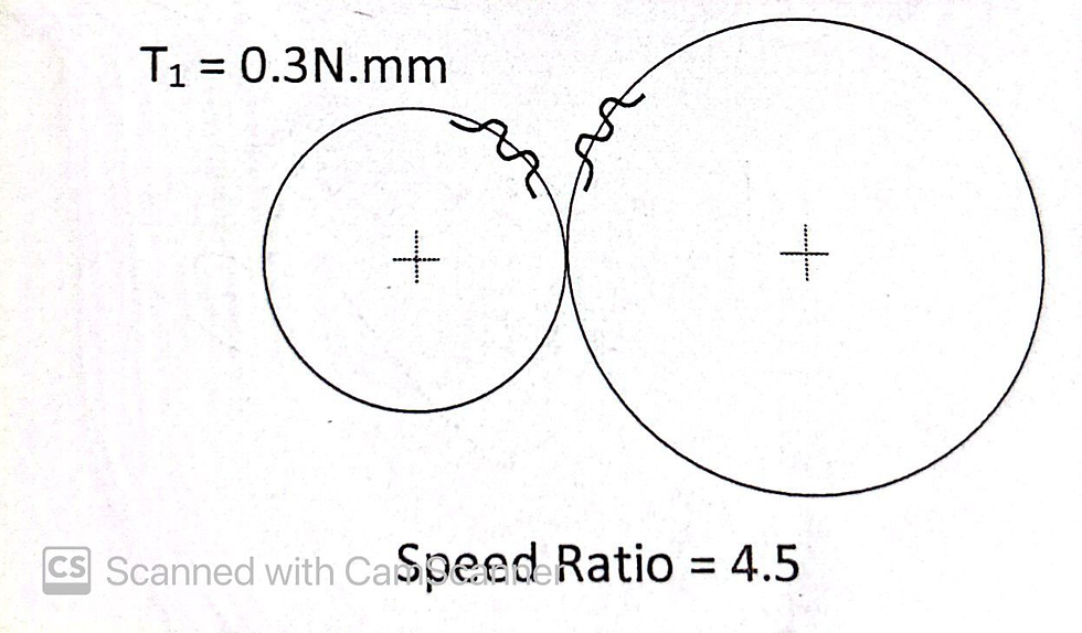
T2/0.3=4.5
T2=1.35 Nmm
Method 3:
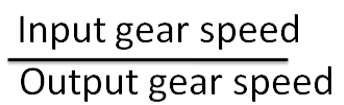
Example:
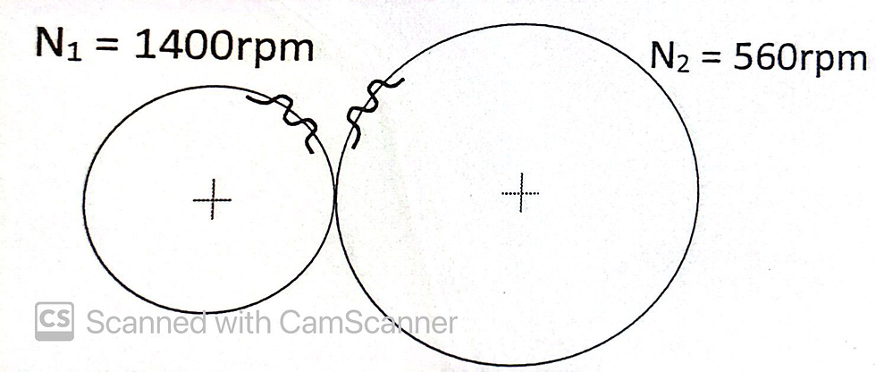
1400/560=2.5
Above are the formulas that can be used to calculate gear ratio.
Relationship between size of gear, speed and force

If larger gear is used to drive a smaller gear, the output speed will be larger as smaller gear turn faster, the output force will be smaller.
It will have lower gear ratio.
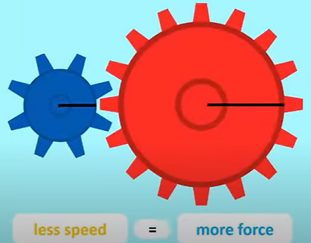
If smaller gear is used to drive a larger gear, the output speed will be smaller as smaller gear turn slower, the output force generated will be larger.
It will have higher gear ratio.
In short, the higher the gear ratio, the bigger the torque, the slower the output speed.
Idler gear
The mechanical advantage of the gear set. It reduces the stress of gears while maintaining the spacing between driven and follower gears.
When idler gear is added, driver gear and follower gear will turn in the same direction.

Type of gear train
Simple gear train
Each gear will drive another gear which driver gear drives the follower gear directly or through an idler gear.
Example:
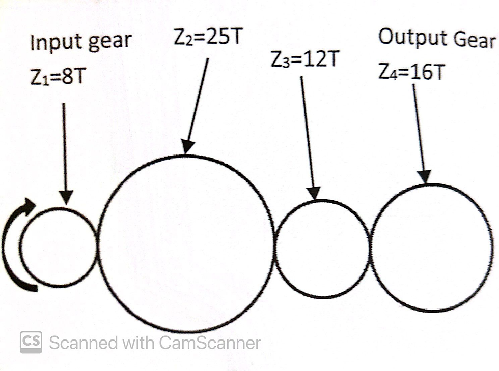
Gear ratio=output/input
=16/8
=2
Compound gear train
At least one gear has 2 or more gears to drive.
Example:
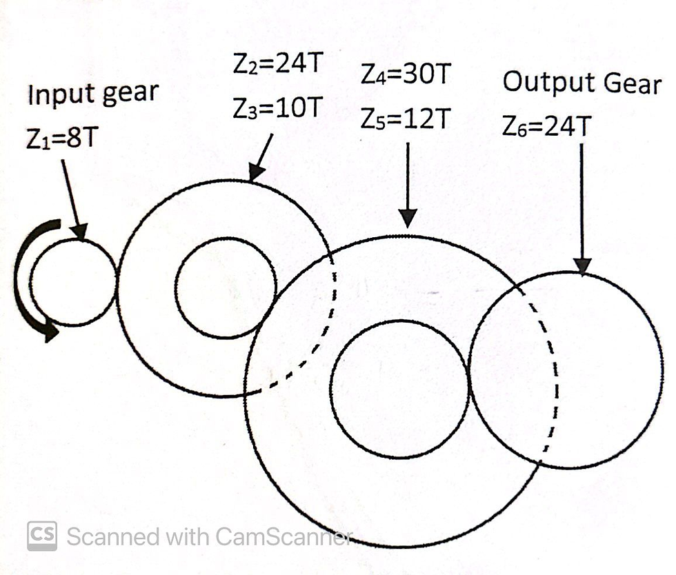
Pair | Output/input | Gear ratio |
1 | Z2/Z1=24/8 | 3 |
2 | Z4/Z3=30/10 | 3 |
3 | Z6/Z5=24/12 | 2 |
Compound gear ratio=3 x 3 x 2
= 18
Gear in Hand Squeezed Fan Project
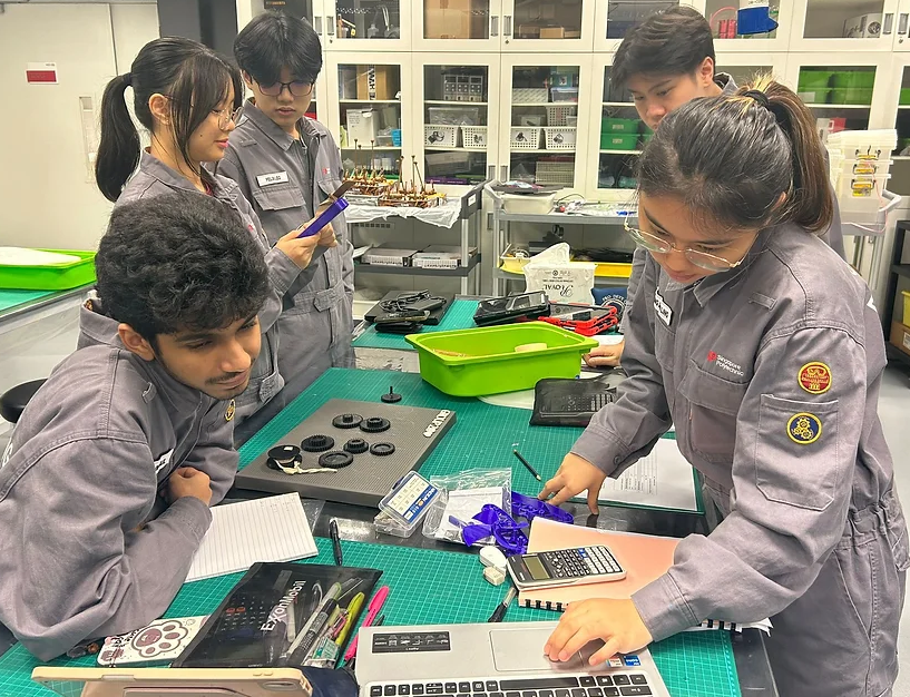
Hands-on Experiment
Let us now be back to the exciting projects that we have done! Me and my teammates were tasked to assemble the hand-squeezed fan with the gears and parts given.
Our objective is to create a mechanism that could generate maximum airflow with minimal effort. By choosing a lower gear ratio between the handle and the fan, we could achieve faster blade rotations for each squeeze on the same direction, effectively increase the airflow. By using the pushing mechanism, the handle will move back and forth, effectively decrease the force needed to rotate the fan.
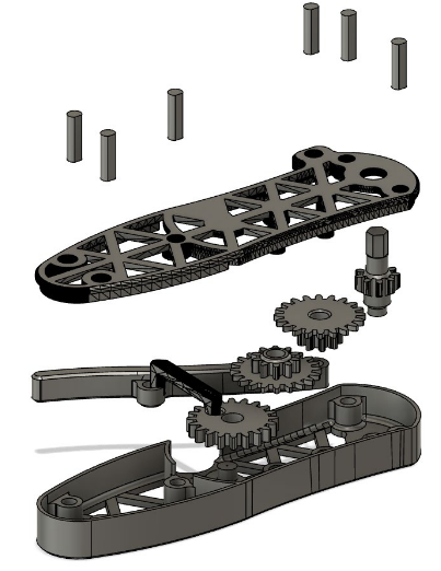
Parts of the hand-powered fan
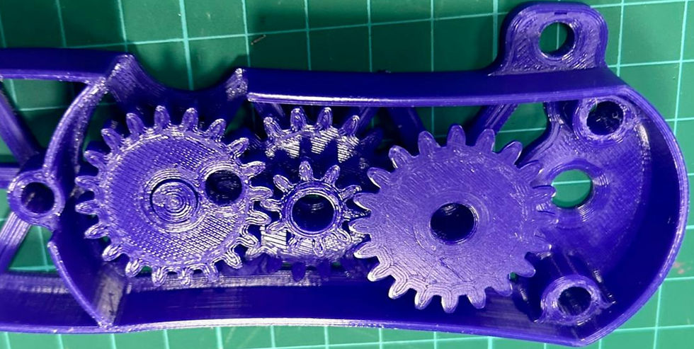
Gear arrangement proposed for hand-squeezed fan
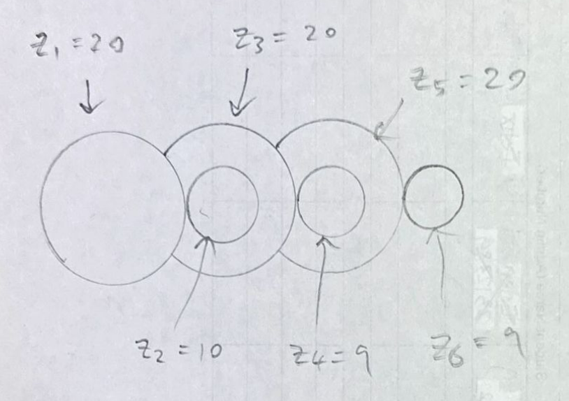
Gear arrangement sketch with number of teeth indicated
The design that my group has proposed is as above. The reason of this arrangement is that we want to achieve as high speed as possible. Therefore, we need a lower gear ratio to obtain the desired outcome of the gear function which is to maximize the amount of cool air produced by turning fan blades.
Gear ratio
Let us calculate the gear ratio of this arrangement. As this is a compound gear, we will calculate each gear pair one by one.
Pair | Output teeth/input teeth | Gear ratio |
1 | 10/20 | 0.5 |
2 | 9/20 | 0.45 |
3 | 9/20 | 0.45 |
Compound gear ratio= 0.5 x 0.45 x 0.45
= 0.10125
From the calculation, it is obvious that the gear ratio is low to increase the speed of turning fan.
Number of Revolutions
Let us now continue to calculate the theoretical number of revolutions every time the handle is cranked.
Number of revolution = 1/0.1025 =9.88 (10 rotation)
Theoretical vs Actual Number of Revolutions
Let us now prove it by our hands-on installation of the hand-powered fan. As you can see from the slow-motioned video below, it took around 10 rotation every time the handle is cranked. WATCH THE VIDEO! HEHEHE
200Hmm from the ground
How can I design a better hand squeezed fan?
Original design sketch
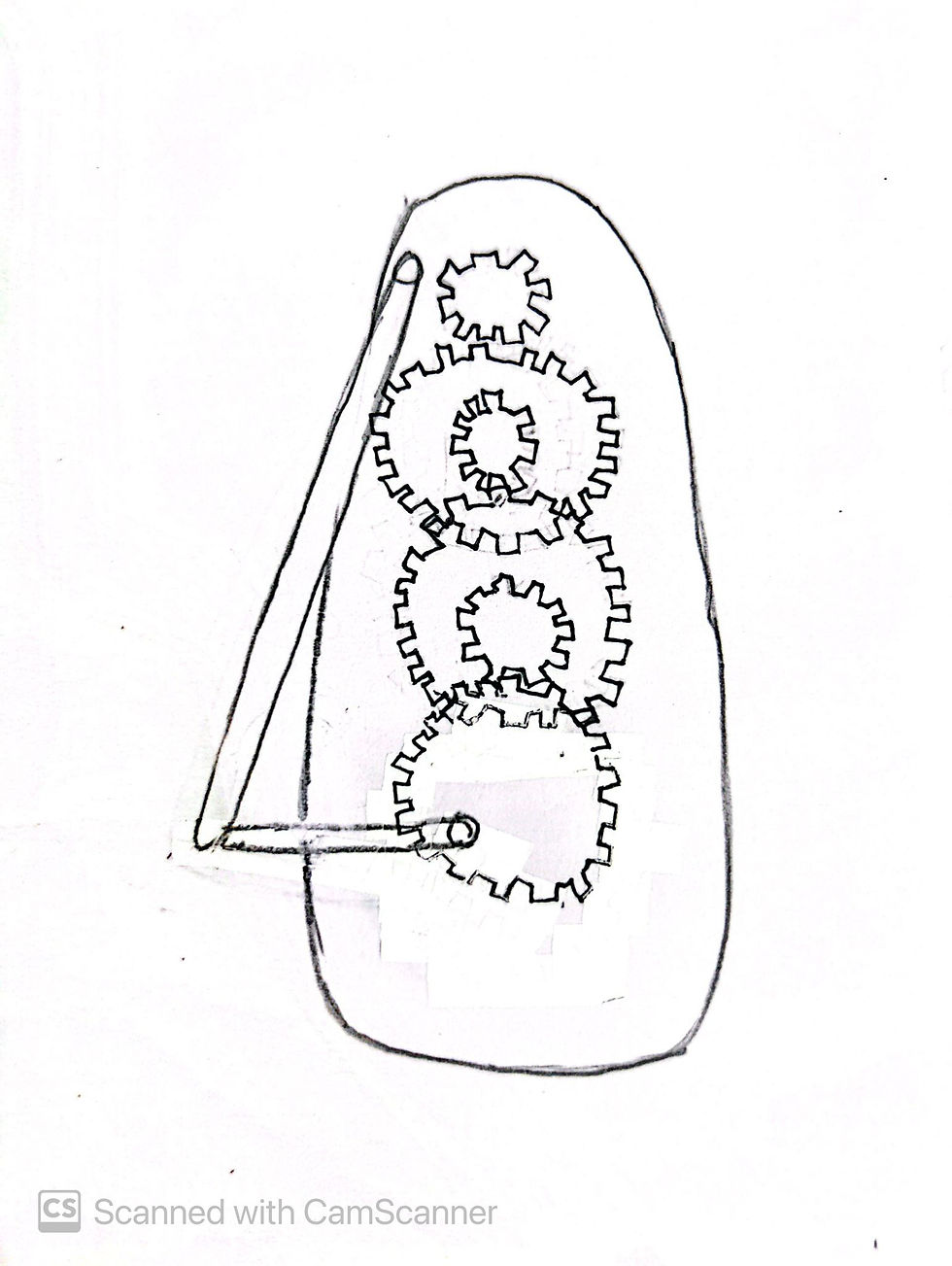
Above are the 2 videos that I took reference from for my modified sketch.
Modified design sketch
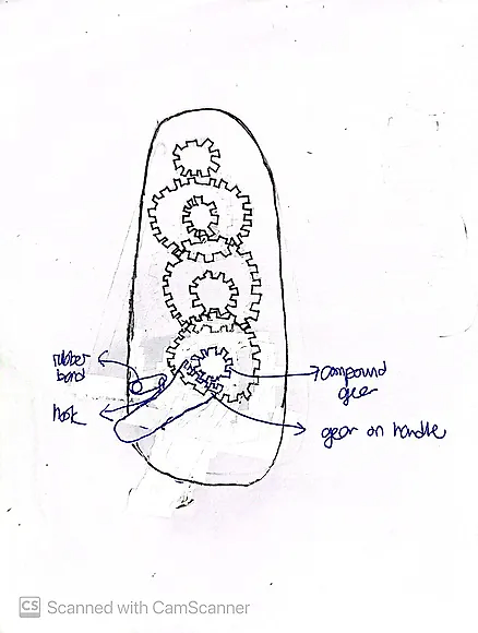
Modification 1: Direct Gear Engagement
By adding teeth to the handle itself, it directly engages with the driver gear, removing the need for an intermediary stick. This reduces the handle angle and the force needed to produce the same rotational movement as the handle now moves with greater precision and efficiency.
Modification 2: Elastic Return Mechanism
The hook on the handle for attachment to a rubber band, spring or another elastic material provides a smooth return motion. Elastic materials like springs or rubber bands are able to store energy when the handle is moved forward. Upon release, this energy aids in pulling the handle back, making the system more user-friendly by reducing the effort required for continuous movement.
Modification 3: Compound Gear on Driver Gear
A small compound gear is added on the driver gear so that less force is needed to rotate fan blades. It overcomes the inertia and allow the fan to maintain a consistent airflow even as the force exerted by the user varies as the gear teeth on the driver gear is meshed to the handle teeth.
Gear in Water Bottle Lifting Project
For the second activity, we were tasked to lift up a water bottle using gears. Our objective was to understand how gear ratios impact force and torque by lifting a water bottle using a series of interconnected gears. To achieve this, our team arranged a set of gears with a high gear ratio, prioritizing torque over speed, which was essential for lifting a heavier object with minimal input force.
Let us work out on the gear arrangement by using the idler and compound gear with different sizes to obtain a high gear ratio.
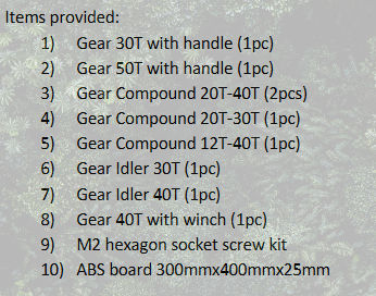
These are the items provided and there are some rules that we need to adhere to in our arrangement.
Only one handle can be used.
All the gears must be used.
Only 2 layers of teeth arrangement is allowed.
Hands-on Experiment
We started by using the smaller handle because we need a smaller input gear teeth to obtain a large gear ratio. We proposed to arrange small input gear and large output gear and vice versa and stack them accordingly by trial and error to get the largest gear ratio. One of the hardest parts in this activity is to make sure the gears do not clash with each other. For example, the 12T-40T cannot be reached if the compound gear has not enough distance to mesh with it.
Eventually this is the arrangement that we have come up with. We used the socket screw kit to set the gears on the ABS board. One of the end of gear is meshed with the handle and another end is meshed with the winch.
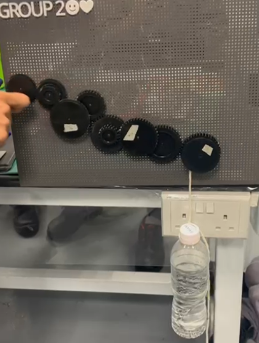
Gear arrangement proposed for bottle lifting
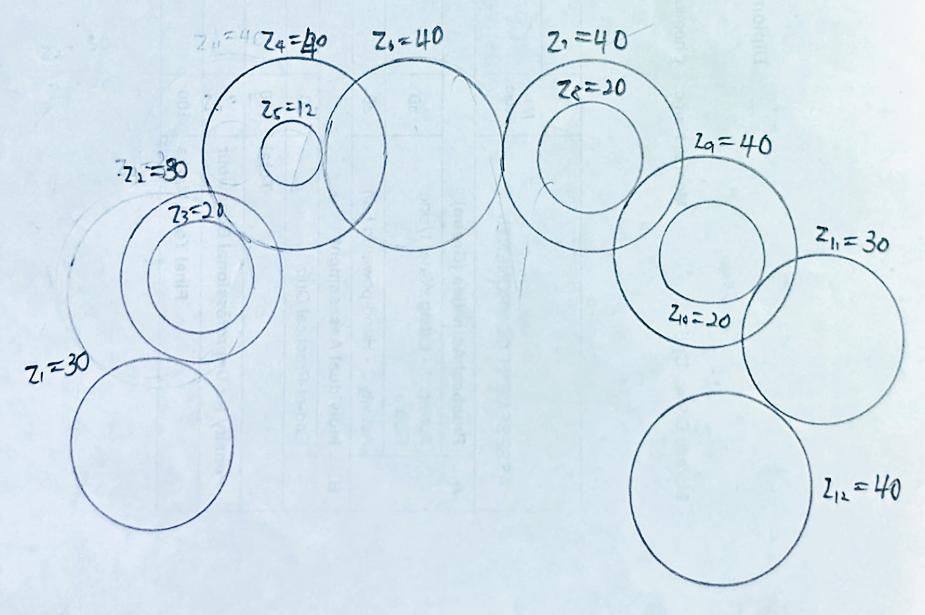
Gear arrangement sketch with number of teeth indicated
Gear ratio
Now, let us calculate the gear ratio of our design.
Pair | Output teeth/input teeth | Gear ratio |
1 | 30/30 | 1 |
2 | 40/20 | 2 |
3 | 40/12 | 3.33 |
4 | 40/40 | 1 |
5 | 40/20 | 2 |
6 | 30/20 | 1.5 |
7 | 40/30 | 1.33 |
Compound gear ratio = 1 x 2 x 3.33 x 1 x 2 x 1.5 x 1.33
= 26.67
Number of revolutions
Let us continue to calculate the number of revolutions required to rotate the crank handle to move the bottle up by 200mm from the ground. I am going to explain this in a sequence of steps as below:
Measure the diameter of winch with rope.
3.325 cm
Measure the diameter of winch without rope.
2.969 cm
Take the average diameter of the winch.
(3.324 + 2.969)/2 = 3.147 cm
As 1 revolution of winch will move the rope by πD (D= Diameter of the winch), use the distance of bottle divide by 1 revolution of winch and multiply by the gear ratio, we will get the number of revolutions of the handle.
20(26.67)/3.147π = 53.95 (54 revolutions)
Theoretical vs Actual Number of Revolutions
Now, let us take a look at the actual number of revolutions that shown in the experiment video that we did. WATCH THE VIDEO! HEHEHE
The number of revolutions in the video is 65 revolutions which is slightly more than our theoretical calculated value. Why is that so?
We have found out that our length of rope is not accurate, it is 3cm longer than the length required in the experiment. This is due to human error that we did not measure the length precisely and it caused our experimental result deviated.
Reflection & Conclusion
After this practical, I am able to:
1. Identify the relationship of gear ratio and number of teeth, pitch circular diameter and torque.
2. Calculate the gear ratio of a gear train.
3. Choose the right gear ratio for torque or speed.
In working with gears, I have seen firsthand how the right gear ratio can be the key to achieve the ideal balance between speed and torque—whether it is for powering a hand-squeezed fan or lifting a weight. This hands-on experience has deepened my understanding of how each element in a gear system works together and showcase the importance of precision and planning in design.
Reflecting my team's performance, there are areas that we could improve. One major insight is the importance of precise measurement specifically the rope length for the bottle lifting in this experiment. As we didn’t measure it accurately, the actual number of handle revolutions needed to lift the bottle deviated from our calculations. Moving forward, we would ensure precise measurements and check calculations early in the design process to enhance the work quality and efficiency of teamwork.
Moreover, our team find it hard to balance the gear layout for efficiency without causing parts to clash. When arranging the gears for bottle lifting, we had to carefully consider the space and alignment of each component. For the fan, we focused on optimizing speed, while in the bottle lift, torque was our priority. However, our team collaboration played a significant role. Everyone contributed ideas and tested alternative solution for different configurations that has ensured smooth functionality without interference.
Gears are not just confined to complex machines, they are literally EVERYWHERE in our life, from household tools to bicycles. By looking closer at the mechanisms around us, we can uncover the elegance of engineering that often goes unnoticed. I invite you to take a fresh look at the devices you use daily and perhaps even explore their mechanics in a simple DIY project. It will be rewarding to bring engineering concepts to life!

Comments