

Blog 4: Project Development

Finally, we have reached the heart of our module, which is project development! From the initial design process to the hands-on work of building our device, has definitely gave us a good exposure on learning, integration and teamwork. Without further ado, let me introduce you my team's device for this project.
Our Chemical Device
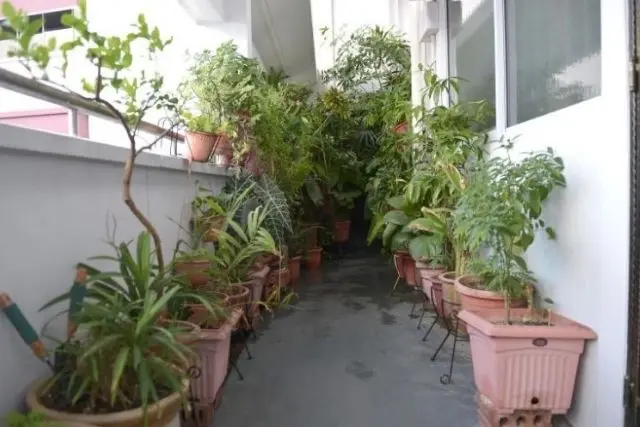
Our device is an automated plant watering system, created in response to a common issue many people face in Singapore. It’s popular for residents to have plants along the corridors of HDB flats or condominiums, but due to the fast-paced lifestyle here, they often forget or neglect to water their plants. A global trend highlighted by BetterPlanter reveals that 50% of houseplant owners fail to meet the basic care requirements which is forgetting to water their plants!
On top of that, as plant parents, Millennials encounter several difficulties in caring for their indoor plants, leaving them unable to keep them alive. OnePoll and Article revealed that 22% of the 2,000 Millennials surveyed said that they were afraid to pursue caring for houseplants because they’ve accidentally killed at least one.
The Millennial respondents said that the most challenging parts of taking care of houseplants included:
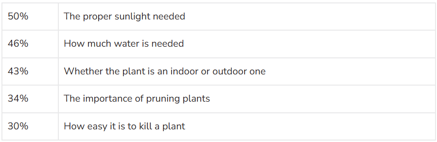
Hence, this inspired us to create a plant watering system controlled by Arduino which it will dispense water when moisture sensor detects low soil moisture level tailored to different type of plants. It helps to keep plants healthy and minimize repetitive physical watering which is convenient for busy plant owner whether they are caught up at work, or away on vacation...our product is designed to meet their needs.
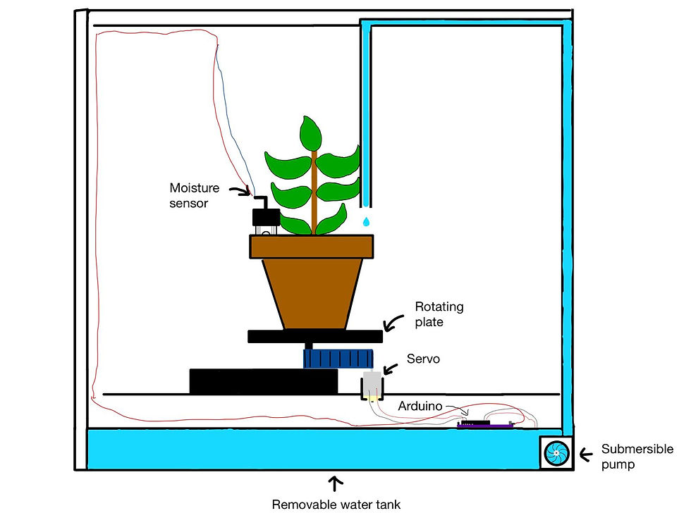
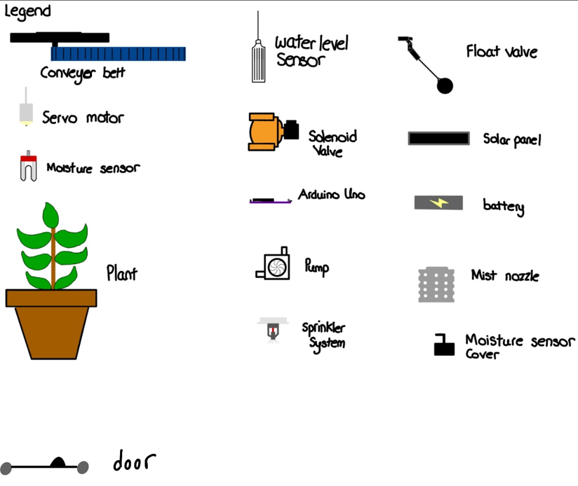
Below is the 2D sketch of our final prototype design which has evolved through a series of refinements during our design process.
Task Allocation, Team Planning and Project Execution
Moving on, I will be explaining on the roles we are allocated, how we plan our budget and how are we going to create this prototype within timeframe. Let me begin by introducing my amazing teammates, each one bringing their own unique skills and expertise to the project. Below is a photo of our team, named Aquautomate.
I’m Zhi Ling, the Chief Safety Officer (CSO), the only girl in this team and I was responsible for ensuring that every action taken by the team was conducted under safe conditions.
The guy beside me, dressed in a red shirt, is Nicholas, our Chief Executive Officer (CEO). As CEO, Nicholas ensured that our aims of the project were clearly defined and met.
Next, we have Hasnain, the man in the white shirt, who is our Chief Financial Officer (CFO). Hasnain ensured that we stayed within budget while maintaining the quality of our work.
And finally, we have Kynan, our Chief Operating Officer (COO). The COO was responsible for ensuring that the project ran smoothly and that tasks were completed on schedule.

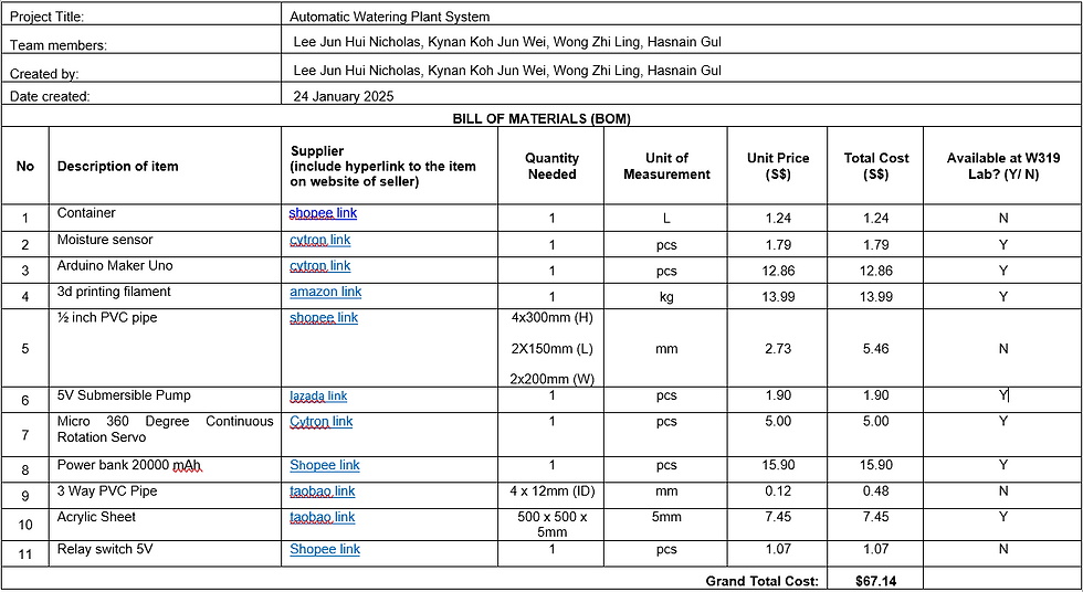
Below is the finalized Bill of Materials (BOM) which show the materials, suppliers and cost needed to build our prototype. BOM serves an important role in development of any product as it helps us to analyze the economic feasibility of our product. Some of its importance are to make the procurement easier, making the purchase of materials more organized so that we will not run out of materials halfway building the prototype which eventually helps on better planning and costing as we can map out the project duration based on the estimated time required for materials delivery, manage the budget of prototype to make sure it falls withing the given cost which is $100. The materials used also evolves from our initial design from CA1 to the final prototype we built, which uses different materials which below is our finalized one.
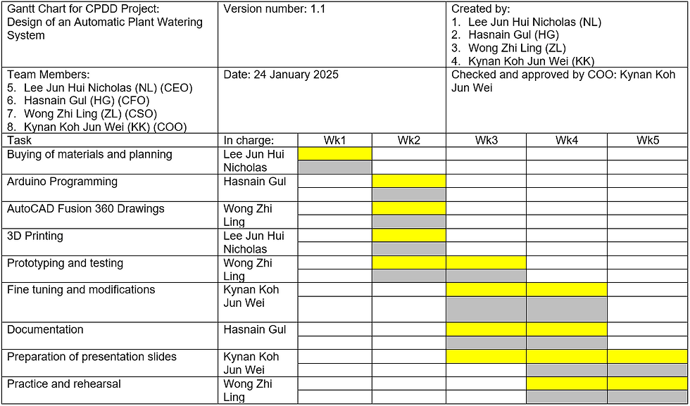
Next, I will be showing the finalized Gantt Chart which shows our timeline to complete the project and how we allocate the task as a team. It is crucial to assess our team's schedule feasibility so that we are able to finish our prototype on time by the deadline. Gantt chart is incredibly useful as it displays our project schedule clearly and simply that allows us to track the status of tasks for every team member. As you can see from the chart below, our team did follow every timeline that we set and everyone were on track. We distributed the tasks and everyone plays a role to be responsible for respective parts to make sure everything goes smoothly.
Design Process
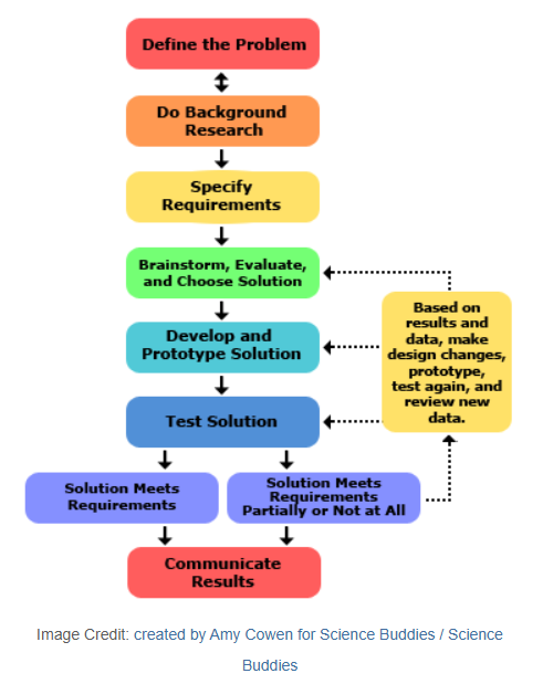
For design process, we use the systematic design method which is introduced in this module.
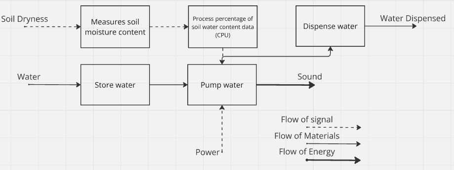
With the problems and background explained above for our chemical device, what will be the detailed function of our prototype?
Based on the CA1 feedback from lecturer, we have changed the CPU connection to "pump water" instead of "dispensing water" and change the power arrow into flow of signal. And this is the updated version!
I will continue on the specific requirement of our automated plant watering system. Below is the specification table of our product.
Table 1: Product Specification Table
Description (Qualitative) | Value and Unit (Quantitative) |
Sufficient water storage capacity | 3-4L |
High water efficiency | 100% of water is transferred precisely to plants |
Mini portable powerbank for power source | 5V |
Low energy consumption | 1-3 W |
Light weight | < 1 kg |
Soil moisture sensor range | 10-100% |
Minimal noise output | < 40 dB |
Low budget on maintenance | < $20 / year |
Low construction and material cost | < $100 |
Maximum operating temperature | 40Oc which is suitable for exposure of sunlight along the corridor |
High durability material for outdoor sunlight resistance | PVC pipe |
Next, we had brainstorm as a team to figure out possible design of each function to meet the specification required by using a morphological chart.
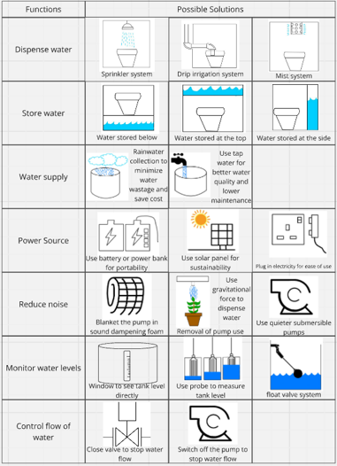
We then use the concept evaluation matrix to analyze and choose the most suitable design based on different combination of the functions that we have brainstormed.
Based on lecturer feedback on CA1 again, we had modified our table into the correct format as well!
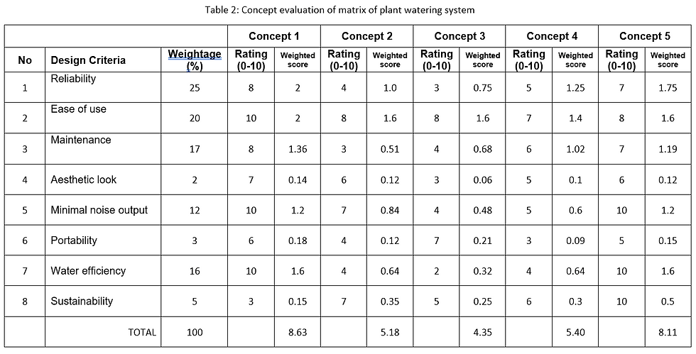
Therefore, based on the score analyzed from different aspect of criteria, we have decided to choose concept 1 which gives the highest score and theoretically best suited as the design to build. Below is the function used in concept 1 and its sketch.
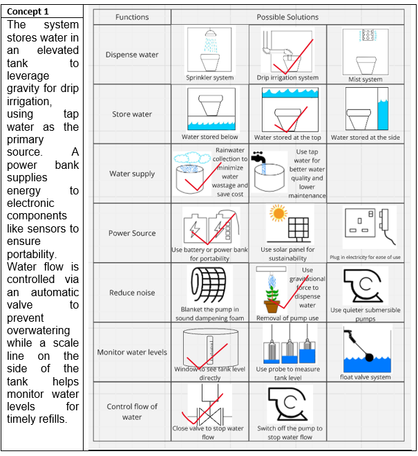
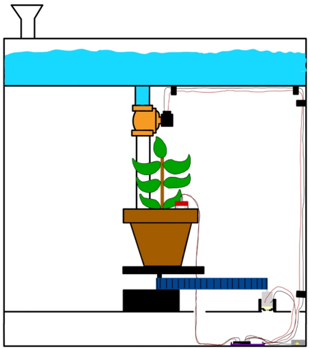
You will realized that this is different with our final design sketch but why?
Looking back at the systematic design process flow chart, we have made design change after several considerations for developing the prototype.
Use pump instead of valve to control water flow
The solenoid valve requires 12V power supply to function which require high energy consumption that does not align with the aim of using solenoid valve to control water flow by gravity that require low power supply. Secondly, the Arduino can only give a maximum of 5V power supply. When external power socket is needed, it decreases the portability of our prototype. Moreover, drilling hole at the bottom of water tank might cause water leaking which will make our prototype harder to build. Hence, we decided to use a 5V submersible pump that is smaller, lighter, and require lesser energy consumption.
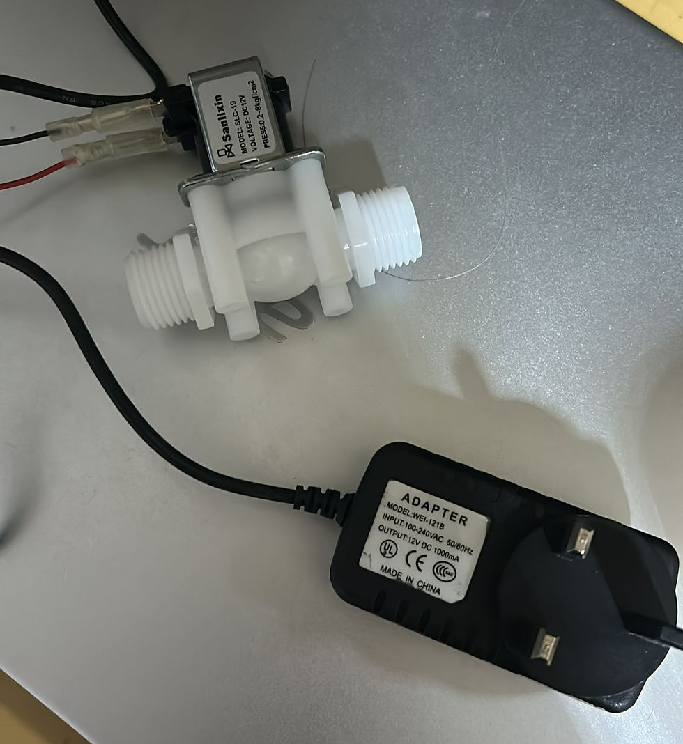
Figure 12: Solenoid Valve with 12V Adapter Locate water tank at the bottom instead of on top
Locate water tank at the bottom increases the stability and portability as the prototype becomes more compact. Secondly, for aesthetical purpose, tank at bottom is able to cover all the wires, Arduino boards and relay. Additionally, pump is able to transfer water from bottom to top.
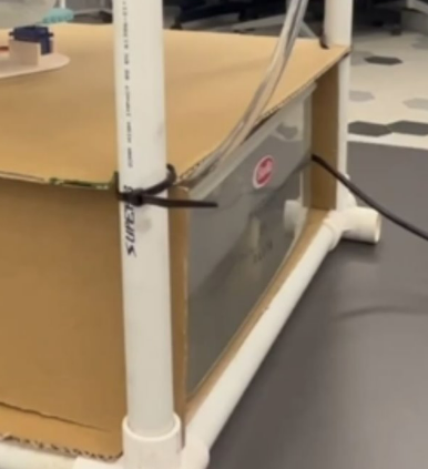
Figure 13: Location of Tank at Bottom Change of mechanism from belt and pulley to gear
Using gear pair is much simpler in building our prototype and it reduces waste of materials.
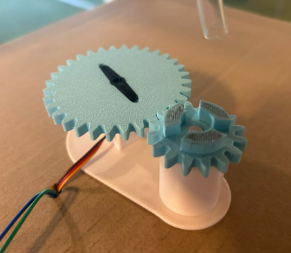
Figure 14: Final Gear Pair Used Addition of sensor cover
We cover the wire connection part of the soil moisture sensor with a 3D-printed cover to prevent it from damage if water accidentally drip onto it.
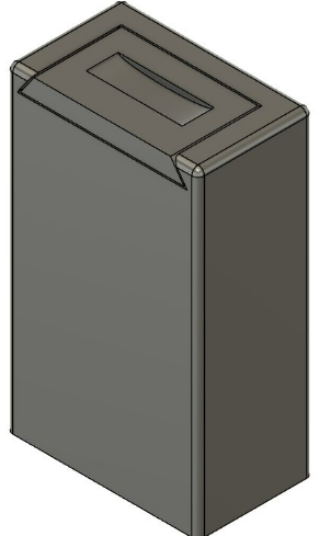
Figure 15: Fusion Design of Moisture Sensor Cover
Now, let us look at how we build and develop our prototype!
My Individual Contribution
I will start off with my individual contribution on this project first. Knowing that I would not be in school the week before submission, I took the initiatives to get the project started early in the first week.
Buying of materials
Based on the initial design, I went to buy the solenoid valve and relay which is not available in our W3 lab as confirmed by the technical executive. I visited several electronic components shop to ensure I picked the correct parts but unfortunately none of them stocked the items we needed. Therefore, I got them immediately from Shopee to avoid delaying our project schedule due to late delivery time. For the PVC pipe, I got it from my house which my mum used for planting. Finding the 3-way connector was quite challenging as well because most hardware stores only carried T-joint connectors, not the 90-degree ones we required. In the end, I bought 5-way connectors as replacement, although it wasn't as aesthetically pleasing. While I do not see sourcing materials as a major contribution, it took a considerable amount of time and effort to have all the necessary materials on hand that is essential for the team to move forward with the project.
Arduino Programming
Once all the components arrived and I collected the remaining parts from W3, I took the initiative to handle the wiring and programming on my own at home during the first week, as getting the prototype to work was a major objective. With the tight timeline of this project, I felt a sense of anxiety to ensure we had a functional setup, especially I might not be able to contribute as much on the week before submission due to other commitments. Although we encountered some challenges along the way, which I’ll explain in more detail later, we successfully finalized the wiring and code, and all components worked as expected.
Video of Pump and Servo Working Soldering Skill Learning
None of us in the team had any prior soldering experience, so we started by watching YouTube video tutorial to understand the temperature settings and how to properly use the coil ring. However, when my teammate Kynan attempted to solder, the coil wouldn’t melt, even though fumes and smell beginning to appear...
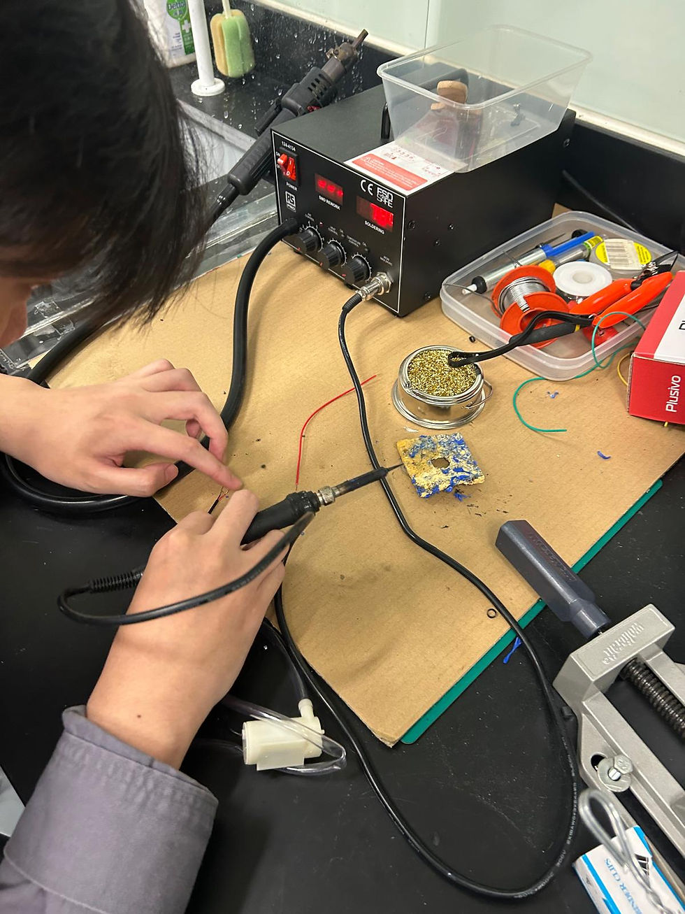
Figure 16: Kynan Soldering I then reached out to Meng Choo, our supportive TE, who kindly helped us with soldering the pump wires. During this process, I also learned to turn on the fan on top to draw away the fumes, as we had done previously. Unfortunately, when I tested on the Arduino later, I discovered that the pump was broken. As a result, I had to solder a new pump at home to replace it...
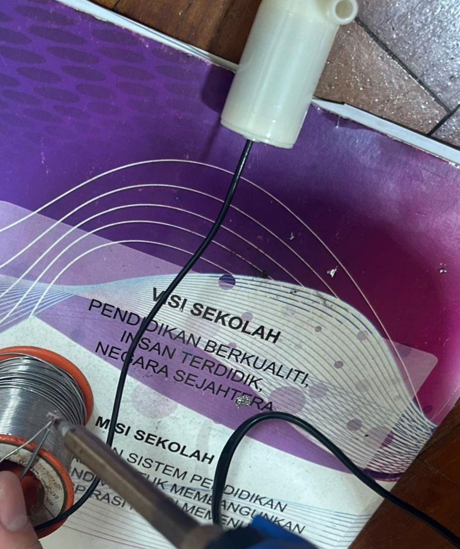
Figure 17: Me Soldering at Home Prototyping and Testing
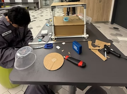
All of us contributed and made the prototype together.
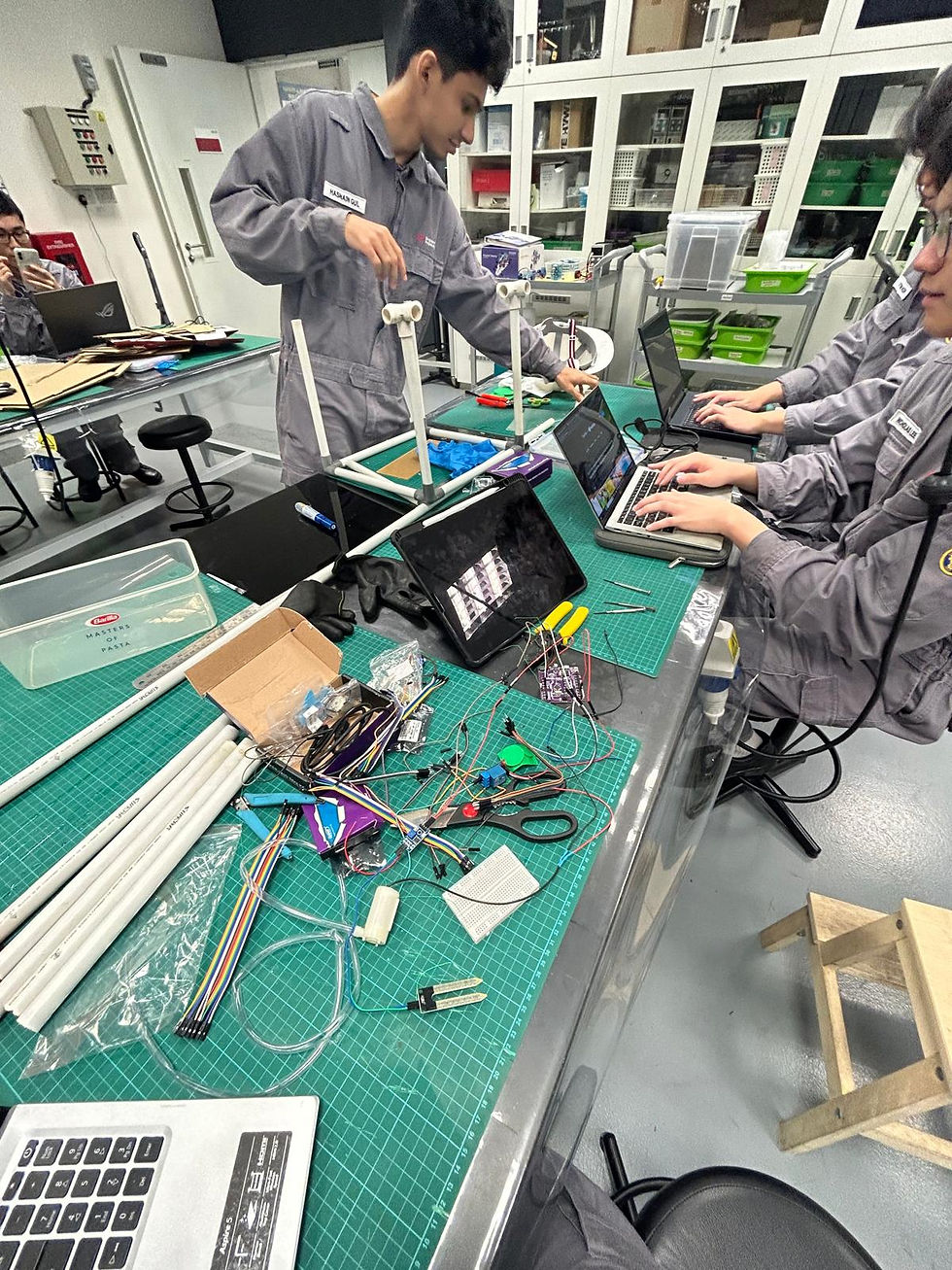
Figure 18: Photo of Everyone Working Fusion on Final Prototype 3D Design
I created the CAD drawing for our final 3D prototype design. My primary motivation was to learn and improve on my 3D modelling skills while contributing meaningfully to the team also especially since my teammate, Hasnain has put in effort in designing the gear mechanism through multiple iterations on Fusion. Creating this final prototype on Fusion was the most fun moment yet time consuming process. Unlike a single-body model where different components are built on the same structure, I had to design and build each component individually before assembling them into a complete design and ensure that each part fit seamlessly.
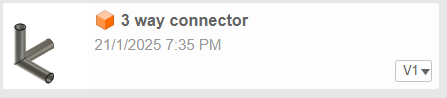
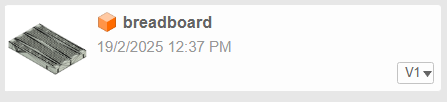
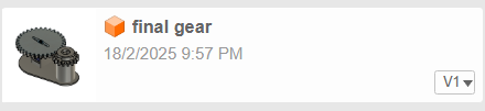
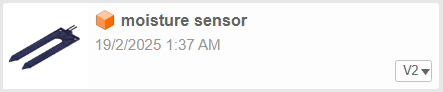
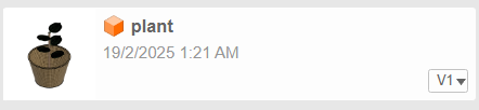

This rewarding experience has strengthened my proficiency in using Fusion, which I became more familiar on the function of Fusion to create what's on my mind from being a complete beginner in ICPD on this app to now being able to create a fully customized design based on our actual prototype that we made! Below is a screenshot of our CAD drawing design which I will embed the 360-degree view fusion file below as part of the requirement of this blog.
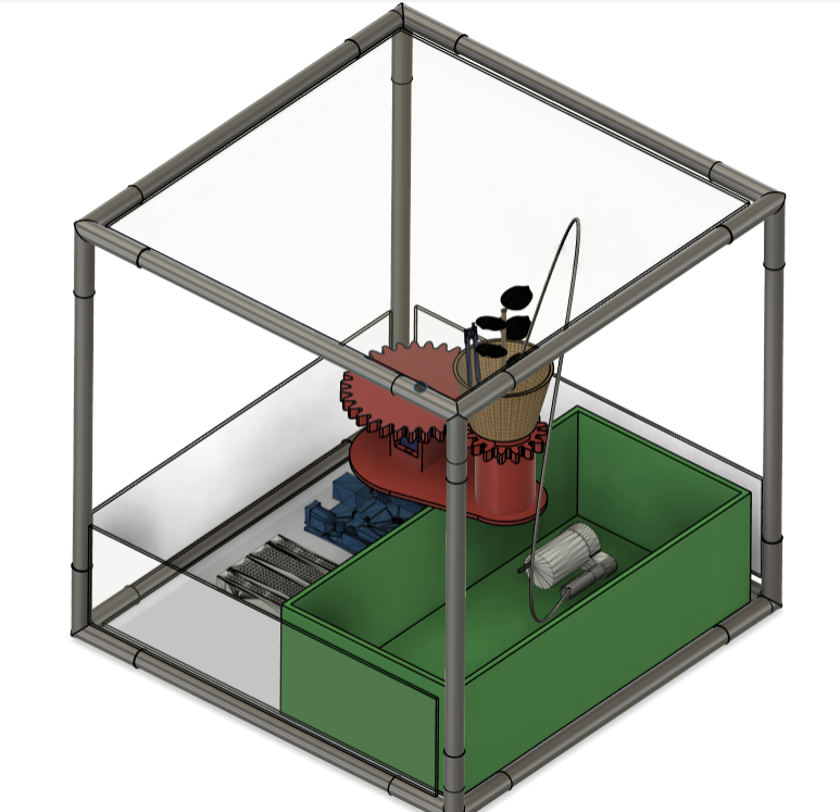
Figure 19: Screenshot of CAD drawing 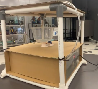
A photo of our actual prototype too! which the cardboard (sustainability) represents acrylic sheet in real product
Building Process
For building process, the skills required are:
Arduino programming,
The code will be uploaded in the google drive for downloadable below for your reference while the physical wiring setup has been reproduced on Tinkercad for better documentation.
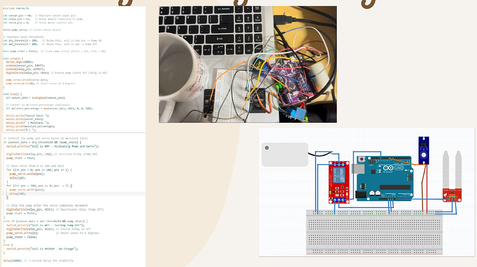
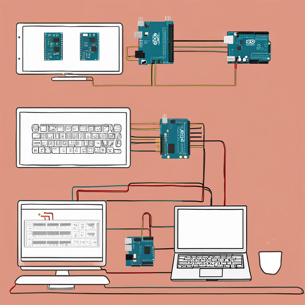
Figure 20: Photo of code, physical wiring setup and schematic circuit diagram This is how our system works. The threshold value is based on the range of the digital output of Arduino from 0 to 1023. Based on the theory when soil is dry, it has higher resistance which is a poor electrical conductivity. Higher resistance means less current flow, thus lower voltage detected. Hence the Arduino ADC will read a higher digital value.
Simply said, when level threshold is:
1023 (5V) = Completely dry (0% moisture)
0 (0V) = Fully wet (100% moisture)
Hence the value is adjustable based on different plant's moisture requirement. For example in our code setup, when:
Soil is DRY (ADC > 600) → Pump ON
Soil is WET (ADC < 400) → Pump OFF
Soil is in between (400–600) → No change
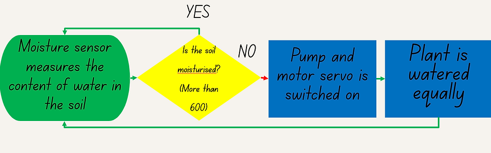
Figure 21: Flow chart of Arduino Components 3D modelling and printing,
Below is the process of evolution of our gear mechanism.
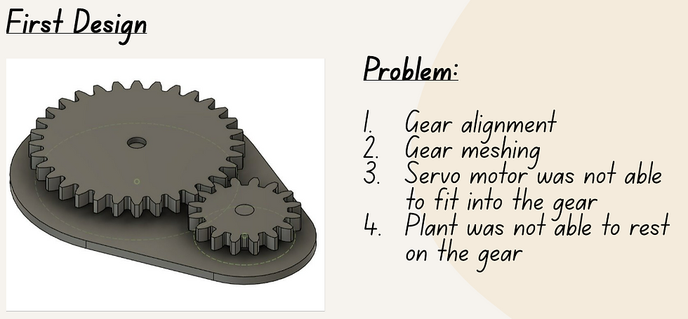
Figure 22: First Design of Gear Pair 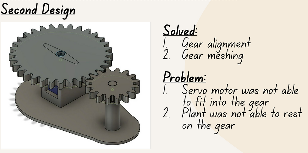
Figure 23: Second Design of Gear Pair 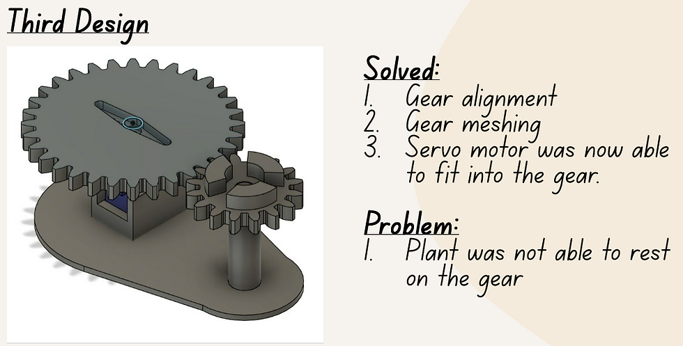
Figure 24: Third Design of Gear Pair 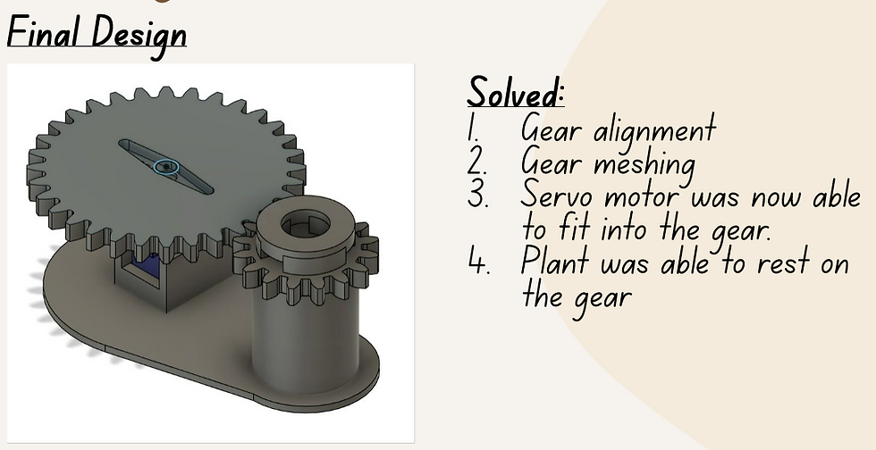
Figure 25: Final Design of Gear Pair And this is the failed iteration of 3D-printed design.
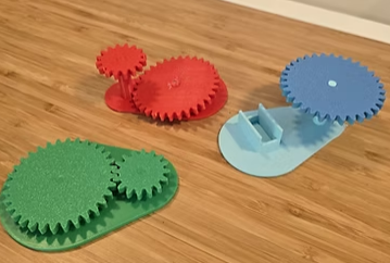
Figure 26: Failed iteration of 3D-printed Gear Design hand tooling.
After the internal parts of prototype is ready, we used hand tooling skill like hot glueing, cutting of pipes and cardboard, soldering of pump's wires.
Below is the video of the prototype that we built using these skills and how it works.
Feedback from lecturer, we should have placed a tape or use non-transparent container as to demonstrate the movement of gear.
We were on track and finished what have to be done based on the Gantt chart that we created. During the week before submission that 2 of us are away, my teammates Hasnain and Kynan have put in effort in fine-tuning and making the prototype aesthetically appealing for system integration. After the week, we made final adjustment on the code (which the movement of gear and water pumping does not synchronize and stop simultaneously) and preparation of presentation.
Problems Encountered and How We Overcame Them
In design process, we did not face any major problems as theory has always seemed easier than making something real. Some of the struggles in design process was that we were unsure about the materials needed to build our prototype which took us to spend some time on discussion. Hence, I will focus on challenges faced mostly on our building process, which required us to make use of the skills that we learnt in product design.
Faulty pump
To be honest, I don't see "faulty pump" as a main issue but rather to me it felt more like a part of broader troubleshooting process, where multiple issues emerged along the way. This was by far the most frustrating part when I was working on the Arduino. Below are the components needed for setting up our prototype.
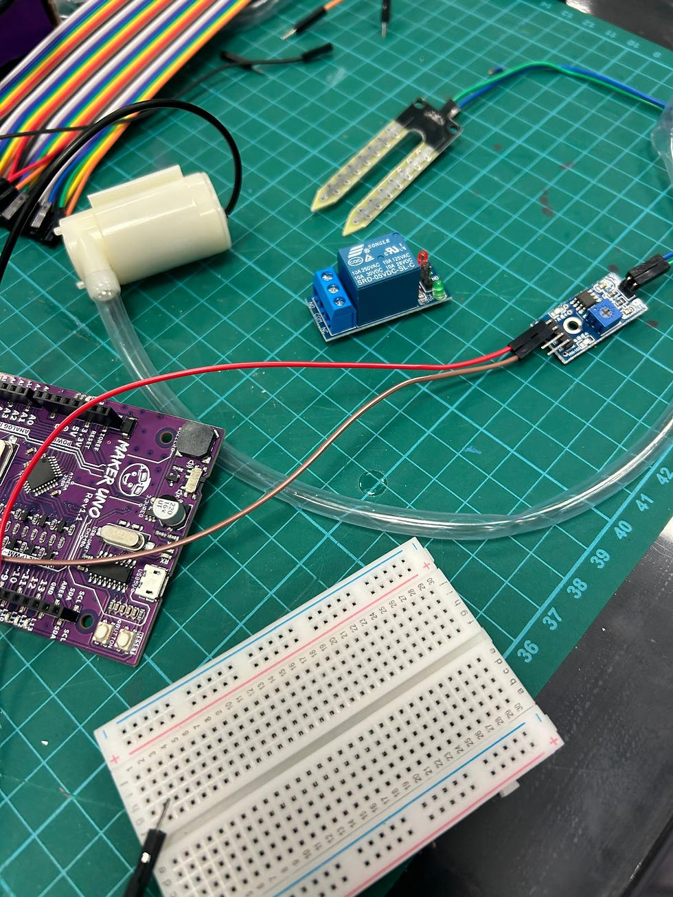
Figure 28: Components needed for Automated Plant Watering Based on prior wiring knowledge that we learnt last semester, we connected the components with +, - or the pin that we knew how to connect. For the components like relay which has multiple input and output, we referred to online resource to guide the wire connection. After ensuring all the components are well-connected, we prompted ChatGPT for a code based on what I need. The code can be successfully uploaded but the pump was not working at all.
Solution: If the code was fine, meaning that the pump should has turned on when everything was properly set up, therefore we began troubleshooting by checking the functionality and correct wiring setup of each component. For relay, since we could not tell if it is working, we tested it with a buzzer, which sounded.
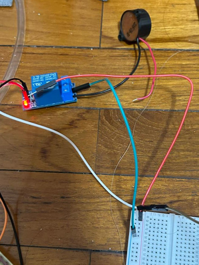
Figure 29: Buzzer Sound Testing We then connected the pump directly to the Arduino to test it, only to find that the issue was with the pump itself. The insulation of the wire had broken, and the pump needed to be submerged in water to function.
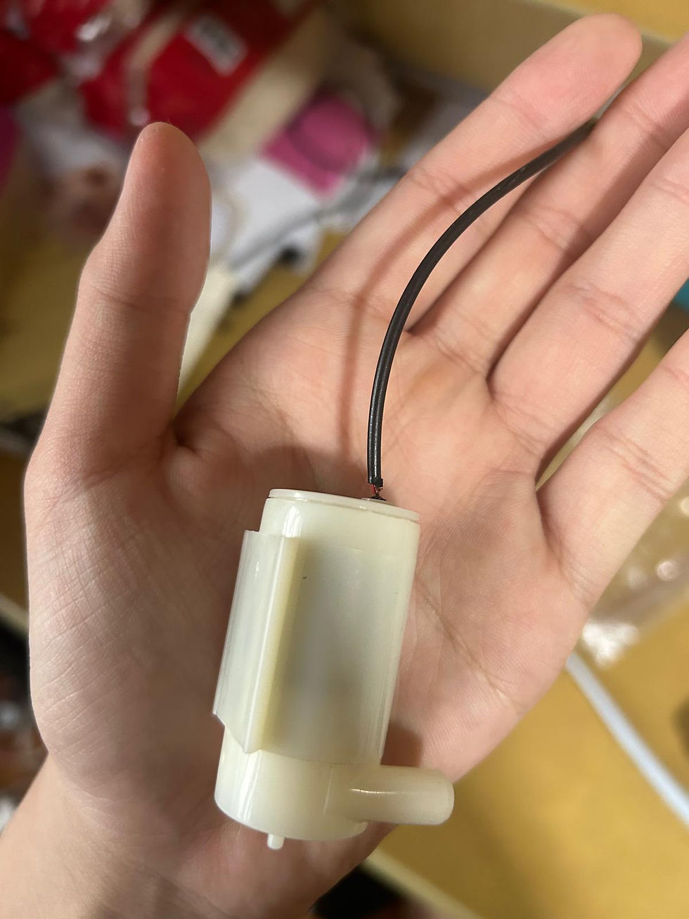
Figure 30: Broken Pump After replacing the pump and reconnecting it, we ran into another minor issue we hadn’t noticed initially: one of the GND pins on the Arduino wasn’t working, which prevented the setup from functioning. We solved this by connecting all the negative pins to a single GND pin on the breadboard. After this final tweak, both the pump and the servo were finally working!
Gear mechanism design
We realized that the when the servo turn 180 degree, we need a smaller driven gear to make the plant turn 360 degree when the driver gear is spined half so that it can be watered evenly and efficiently. Moreover, the servo and plant are unable to be fit onto the gear which causes instability.
Solution: We switched the gear ratio from 1:2 into 2:1. We have also designed a round ring to be attached onto gear and plant. For servo, we have designed a space for it to slot in under the gear which its arm attached to our customized gear for stability.
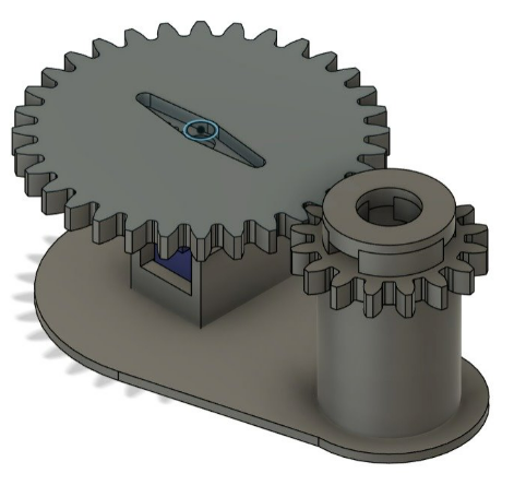
Figure 31: Gear Pair Used for Prototype
Downloadable Files
You can view our Arduino code, gear design of different version from the start to the final one and our final prototype CAD drawing here!
Final Prototype Design File
This file displays every component which is exactly the same with our product including Arduino motherboard, breadboard, relay, gear, pump, moisture sensor, pipes, tank and the plant. Hopefully it looks cool, but it really takes quite some time to build each component and coordinate everything into a single 3D design.
Due to too many components of this CAD design, it might take a while to load 😀
Feedback from our lecturer, there is still room for improvement on limitations of our prototype, which are:
1. Placing the Driver Gear Below the Driven Gear
Currently, our gear pair design places the driver and driven gears side by side, which is not ideal for supporting the weight of plants, especially those with moist, heavy soil. The weight of the plant can increase friction, making it harder for the servo motor to turn the gear.
Suggested Improvement: To address this, we could place the driver gear below the driven gear. This would reduce friction, making it easier for the gear mechanism to function smoothly. Additionally, by positioning the driver gear below, we would improve the limitation of power efficiency of the servo motor.
2. No Acrylic Sheet on Top
Our current design placed an acrylic sheet placed over the top of the plant. While adding an acrylic sheet could protect it from external factors, it could hinder plant growth by blocking light and restricting airflow and spaces to growth.
Suggested Improvement: Eliminate the sheet on top to maximize the space for plant growth.
3. Directing Water Flow Through Pipe Instead of Tube
Our prototype currently uses a tube to direct water from the pump to the plant. However, this setup introduces issues with the tube swinging around, potentially watering unevenly.
Suggested Improvement: We could utilize the PVC pipe rack, which already serves as the support structure, to guide the water flow more precisely. By slotting the tube connection from the pump into the pipe, we can prevent the tube from swinging and ensure that water is directed more accurately to the plants. This change would also eliminate the need for a top cover to support the tube, simplifying the design and improving functionality.
4. Testing the System with Wet Tissue Instead of Water
In our prototype testing, we used a water to simulate moisture conditions. While this was a quick solution, it doesn’t realistically simulate the actual conditions of plant in soil.
Suggested Improvement: To improve testing accuracy, we could use materials that better represent the moisture levels in soil, such as a sponge, wet tissue or another absorbent material. This would allow us to more effectively test the moisture sensor’s functionality and demonstrate the system’s performance under more realistic conditions.
By implementing these improvements, it can enhance the functionality and realism of our prototype, so that it is more practical and aligned with the needs of plant owners.
Personal Reflection
Since the learning process, challenges we faced and how we solved them has been explained in the earlier section, I will reflect on this project as a whole instead of the prototype work.
This phase of project was a big shift for us that pushes us to design and build a functional prototype, which turns our ideas into something real! It is not just about applying the incredibly useful skills that we have learnt from ICPD last semester and this CPDD module but also figuring out how to handle failures, troubleshoot problems encountered and improve our project along the way. In terms of technical skill, I have really learnt a lot through this project such as gaining deeper understanding on Arduino wiring setup connection, troubleshooting on Arduino code and enhancing my Computer-Aid Design skill by reproducing the entire product of our prototype on Fusion which I am glad that I am in progress towards the goals that I have set at the beginning of this module. There is still a lot of things and areas which I need to learn and improve on.
Beyond technical skills, this session also emphasizes on how we coordinate the project planning and collaborate with our teammates that strengthened our ability to communicate effectively and work cohesively with each other. I have understood that planning a project is always not easy as it seems, we had to juggle tasks, coordinate schedules and make sure everything came together on time. This experience gave us a glimpse of what is coming in our Final Year Project (FYP) where we will have to handle even bigger challenges. This session has truly pushed me to become more determined and self-driven when I need to search for information to complete our project, understand unfamiliar concepts on the skills required, and coordinate online resources, especially when we had to build everything from scratch. Through this project, I have learned to set high expectations for the quality of my work and pay greater attention to detail, striving to do my best in every aspect. This became especially important after we lost track of quality in the second segment of our project. From this, it is also about how we see our project from different perspectives, identify the shortcomings and improve it actively.
From this project development, the main thing I need to reflect on is the unstable work quality from me and my team. I have come to realize that teamwork is really important as a group project definitely cannot be done by one man. We have seen our weakness in building process compared to the design process in CA1. During CA1, we worked closely as a team, meeting up often, discussing everything and making sure our work hit all the rubric points. That approach helped us produce a solid work done. However in CA2, due to everyone's schedule of being busy with other assignments and the fact that 2 of us were unavailable for the entire week before the submission and presentation, we divided the work and focused on getting different parts done individually while keeping to deadlines. This indeed helped us to build a working prototype, but it led to us overlooking each other's parts, missing out on discussions, and not progressing together as a team. There was a lot of improvements which we could have made but we did not, for example, on the presentation slides, we did not fully explain our design process from CA1 which we missed out to include the morphological chart and concept evaluation matrix while on the prototype itself, the system integration of sensor and servo wires were still exposed instead of being tucked inside the PVC pipe while we kept most of the wires hidden at the bottom.
Even though our final product was not perfect, the whole process was a learning experience and a WAKE-UP CALL for us. I believe we have learnt our lesson and that made us to realize that we cannot afford to do the same in our FYP. I am determined to take what I have learnt here and do better next time. Rather than just aiming for completion, we need to focus on producing high-quality work that reflects our full potential. Moving forward, I am committed to putting in my best effort to ensure our FYP is executed with greater attention to the details, be more proactive to ensure that every aspect of our work is refined.
No matter what, I still feel incredibly fortunate to be part of such an amazing team. From the very beginning, each of us has approached every task with determination and a solutions-focused mindset, making even the most difficult problems feel much more manageable. Everyone consistently demonstrates a strong commitment to the project and works efficiently. From the bottom of my heart, I’ve learned so much from them, not just in terms of technical skills, but also in how each person, with their attitude and unique character, handles challenges and failures. As a group, we learned together, failed together, and ultimately grew together. This project would not have been possible without the contributions of every team member—Nicholas, Kynan, and Hasnain. (Hopefully yall did read my blog also, Thank you! From the bottom of my heart. This is our first time working together as a group and I hope we continue to develop a better teamwork and keep up the good work, looking forward to collaborating as a team again in our FYP next semester.)
After writing countless of reflections in this module, I actually realized that reflection is really an important phase that help me to recap and summarize everything that I have learnt as I need to refer to the information again when I was writing the blogs, although it is time-consuming and sometimes frustrating, it gives me deeper understanding of my personal progress since most of the work are done in a team. This blog is indeed the longest reflection that I have written but since it is the final and most important one, make sense... Throughout this module. this is the part which "messed-up" the most yet learnt the most thing, leading to so much to reflect on.
And with that, my CPDD blogging journey comes to an end! Wish me all the best as I step into the next episode of my product design journey from ICPD to CPDD, and now onto and exciting and uncertain FYP. To anyone reading this, I wish you happiness and healthy always with my most sincere blessings too!
Thank you for your time!
Comments