

Blog 2: Arduino Programming

Updated: Jan 18, 2025
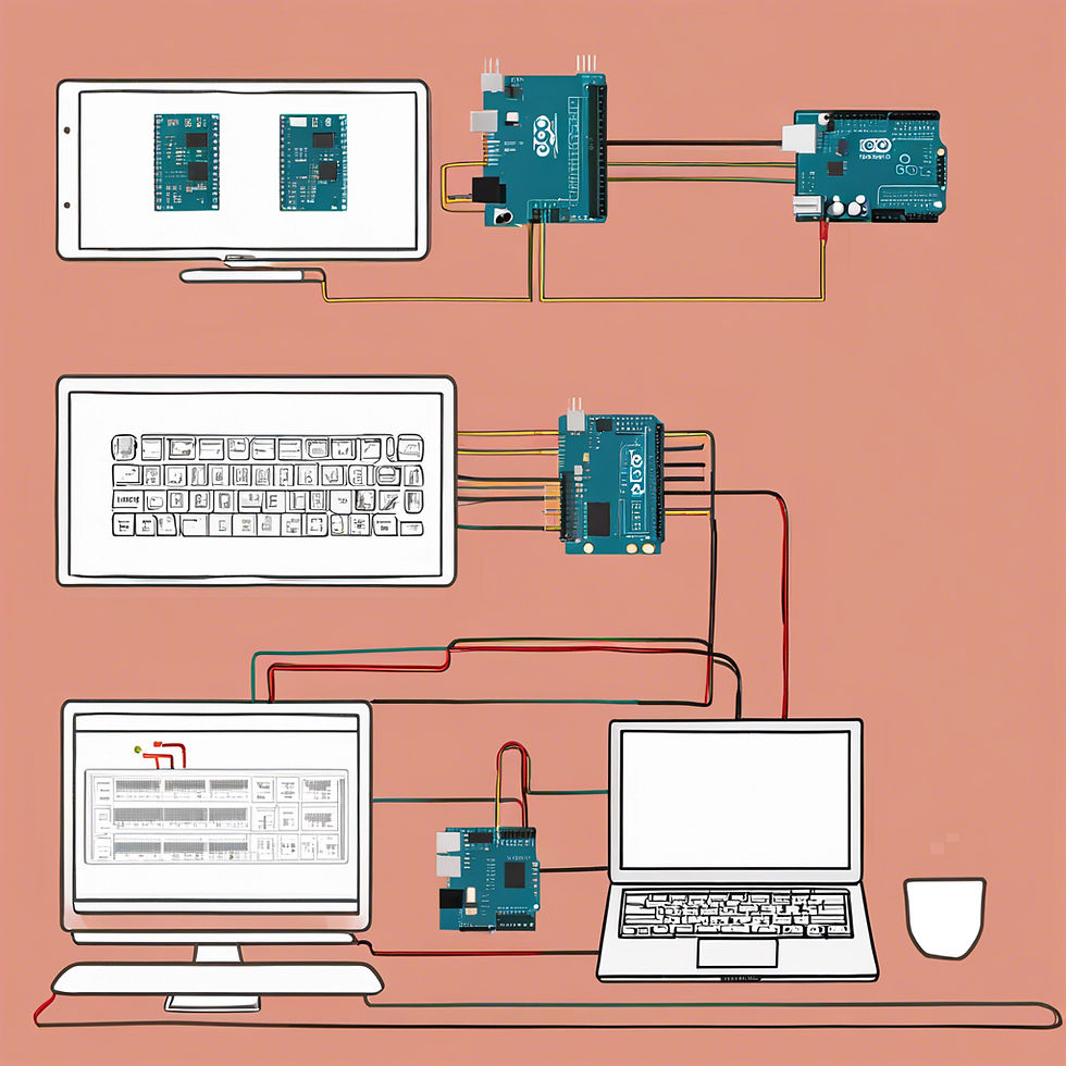
Yo, welcome back to my blog! I am embarking on a journey to learn Arduino from scratch. Before this, I did not know a thing about Arduino, just know that it is a powerful platform for DIY electronics. Arduino is generally considered one of the easiest ways to start programming. However, Arduino is not a separated programming language, it uses a simplified version of C++ with many built-in functions so that beginners can get started without needing an extensive programming background. I will be sharing my learning process, the challenges I faced and the little successes along the way. If you are new to Arduino, hopefully this blog can be a helpful resource as I am writing this from a 100% beginner perspective. Let us learn together!
Before I dive into my content, I would like to encourage you to read through the document above if you are a newbie like me because I find it very useful when I started to learn Arduino programming in this module. This guide is intended for beginners to build foundational skills in programming and electronics using Arduino-compatible boards.
Learning Arduino consists of 2 main parts which are the coding and schematic diagrams for hardware connections.
Coding
Before we connect any wires, let’s talk about the code because understanding the programming is key to making the hardware come alive. First thing first, you have to download the Arduino IDE where you can write, upload and debug code.
This can be found here: https://www.arduino.cc/en/software .
Depending on your laptop, download WINDOWS/MAC zip file and unzip it.
Once installed, select board and serial port.
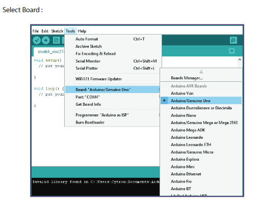
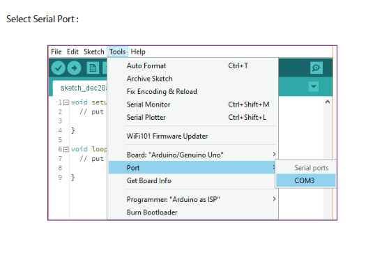
You are now ready for coding! Know nothing about how to start? Use the examples given in Arduino or AI tools like ChatGPT will definitely help.....
Hardware Connection
To make a physical visualization of running the code, we should first get to know about the components in maker-uno board as shown below.
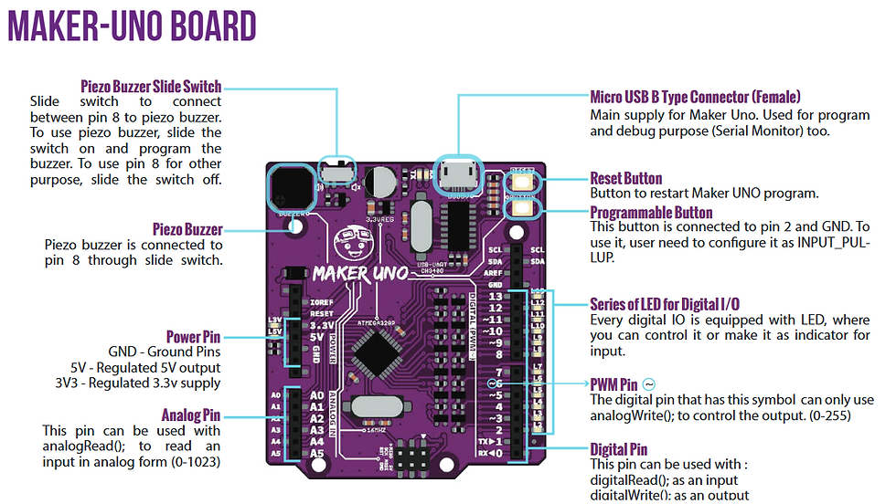
Other than the motherboard, below are the maker-uno Edu kit that provided for wiring to function like motor, LDR, potentiometer, LED and so on.
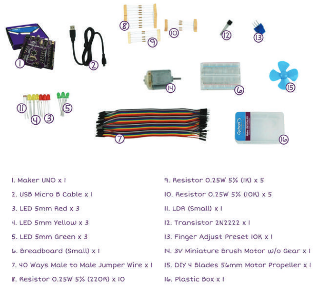
Input and Output Devices on Maker Uno Board
After understanding about the basic of coding and breadboard connections, I will now move on to the core content of this blog, which is the input and output device. We were tasked to do either potentiometer or LDR of the input devices. However, I believe practice makes perfect so I tried to do both wiring setup and code.
The first activity is to interface a potentiometer analog input to Maker UNO board and show its signal in serial monitor Arduino IDE.
First thing first, what is potentiometer?
Potentiometer is a type of variable resistor with 3 terminals that adjusts the amount of current flowing through a circuit. For example, some of its functions is to adjust the LED brightness or speed of servo motor.
Does this diagram and code below look familiar to you?

int sensorPin = A0;
int ledPin = 10;
int sensorValue = 0;
void setup()
{
pinMode(ledPin,OUTPUT);
}
void loop()
{
sensorValue = analogRead(sensorPin);
digitalWrite(ledPin, HIGH);
delay(sensorValue);
digitalWrite(ledPin, LOW);
delay(sensorValue);
}
Yes, if you have read through the document that I attached above, it is actually the same in the tutorial of Lesson 8: Potentiometer Analog Input.
For wiring connection,
Connect the middle pin of the potentiometer to the A0 pin on the Maker UNO board.
Connect one of the side pins of the potentiometer to 5V.
Connect the other side pin of the potentiometer to GND.
Why does the setup example connect each pin to the positive and negative bar before connecting 5V and GND respectively?
It is not necessary in this setup as this is a simple connection. However, understanding that it helps to connect every pin for each pole if there are multiple accessories involved, which we will be using it later in the output task.
However, the challenge has come...
The code provided in lesson 8 involves LED to show the LED blinking speed instead of showing its signal in serial monitor Arduino IDE.
SO, how to show the signal in serial monitor?

Recalling the lesson 6 in the file that I attached above, look for this symbol below in your Arduino IDE on the top right corner.

The serial monitor will appear on the bottom of your screen in Arduino. You will be able to see the changes in value when your potentiometer is working.

Therefore, the provided code didn't meet the requirements for this task. But guess what? AI came to the rescue! This refined code from ChatGPT works perfectly!
This is the revised code for the setup to show signal of potentiometer value on Arduino IDE.
// Define the pin connected to the potentiometer
const int potentiometerPin = A0;  // A0 is the analog input pin

void setup() {
  // Initialize serial communication
  Serial.begin(9600);
  pinMode(potentiometerPin, INPUT);
}

void loop() {
  // Read the analog value from the potentiometer
  int potentiometerValue = analogRead(potentiometerPin);

  // Print the value to the Serial Monitor
  Serial.print("Potentiometer Value: ");
  Serial.println(potentiometerValue);

  // Add a short delay to make the readings easier to observe
  delay(100);
}
I will now explain to you about this code.
const int potentiometerPin = A0; A0 is the analog input pin on the Arduino where the potentiometer's output is connected.
The const keyword means the variable value won't change.
The potentiometer acts as a voltage divider, providing a varying voltage to the A0 pin based on its position.
void setup() {
  Serial.begin(9600);
  pinMode(potentiometerPin, INPUT);
}
Serial.begin(9600) initializes serial communication at a baud rate of 9600 bits per second. This allows data to be sent to your computer.
pinMode(potentiometerPin, INPUT) sets the potentiometer pin as an input, which is the default behaviour for analog pins.
void loop() {
  int potentiometerValue = analogRead(potentiometerPin);

  Serial.print("Potentiometer Value: ");
  Serial.println(potentiometerValue);

  delay(100);
}
analogRead(potentiometerPin) reads the voltage on the A0 pin.
The Arduino converts the voltage (0V to 5V) into a 10-bit digital value ranging from 0 to 1023.
0 corresponds to 0V.
1023 corresponds to 5V
Serial.print("Potentiometer Value: ") sends the text to the Serial Monitor without a newline.
Serial.println(potentiometerValue) sends the actual numeric value, followed by a newline, making it display neatly in the Serial Monitor.
delay(100) pauses the loop for 100 milliseconds, slowing down the updates so the readings are easier to observe in the Serial Monitor.
This is the video of how to interface a potentiometer analog input to Maker UNO board and show its signal in serial monitor Arduino IDE.
You will see the value on serial monitor changes when you turn the potentiometer. When potentiometer is turned into anticlockwise direction, the potentiometer value will decrease to its minimum, 0. On the other hand, when it is turned clockwise, will increase to its maximum, 1023. Turning the potentiometer changes its resistance which the Arduino ADC converts the voltage into value between 0-1023. The maximum value of 1023 is determined by the 10-bit ADC resolution of the Arduino. If the ADC had a higher resolution, the range would be higher which the voltage measurement will be more precise.
Below is the reference source that I found online which is useful for me to complete this task and understand how the potentiometer works in showing the change in LED blinking speed.
And yes, let me introduce you to Tinker Cad, which is basically a virtual Arduino board and all its component. It provides a convenient way to simulate and test your circuit setup to ensure it is correct and functional.
One of Tinkercad's most useful features is its block coding, which allows you to visually design the actions you want to simulate. Once you're satisfied, you can download the generated code and upload it directly to a physical Arduino board. This eliminates the need to write code from scratch, making it incredibly beginner-friendly.
Using Tinkercad, you can test the code provided in the file to visualize how a potentiometer controls the blinking speed of an LED. Simply follow the setup shown in the video and see the potentiometer in action!
When you turn the potentiometer, you will notice changes in the LED's blinking speed. Turning it anticlockwise causes the LED to blink faster while turning it clockwise makes the blinking gentler. This demonstrates that a lower potentiometer resistance results in a faster blinking speed. For instance, turning the potentiometer clockwise increases resistance to ground, lowering the voltage, which in turn increases the mapped delay, causing the LED to blink slower.
Although this isn't covered in the referenced video, let me show you how to view the potentiometer's value on Tinker Cad. Simply switch the block code to text, copy the generated code, and paste it. Start the simulation, open up the Serial Monitor and turn the potentiometer knob to observe the values changing, just like on an actual Arduino IDE and board.
Check out my video example below to see how it works, especially if your partner has taken the Maker-Uno set and you are racing against the clock to finish this blog before the deadline! 👻
The second activity of input device is to interface a LDR to Maker UNO board and show its signal in serial monitor Arduino IDE. I won't go into as much detail as I did in the first activity since the process is quite similar, but I'll document everything useful here for future reference.
Speaking of the LDR, while I know it's a type of sensor, I completely forgot what "LDR" stands for and its purpose. So, I googled it... and guess what? The first result I got was...

ok...I should have searched for " LDR meaning in physics" instead...
LDR stands for Light Dependent Resistor which also known as a photoresistor, is a passive electronic component that changes its resistance based on the amount of light it is exposed to.
The difference between potentiometer and LDR is a potentiometer is controlling the knob manually while an LDR is for responding automatically to light. On top of that, potentiometer has built-in voltage divider mechanism and voltage can be read at the wiper which is from its middle pin while LDR requires resistor to form a voltage divider to convert the resistance variation into a voltage signal that an analog pin can read.
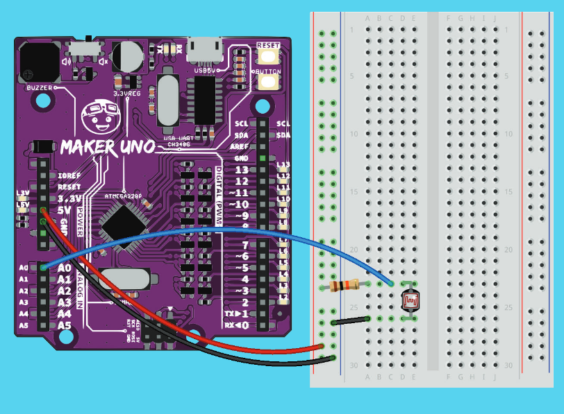
Also the same with potentiometer, LDR as analog input setup is available on the file attached above.
For wiring connection,
One end of the LDR is connected to the 5V pin on the Arduino.
The other end is connected to the Analog Pin A0.
A resistor is connected between GND and the junction where the LDR connects to A0.
The video reference for showing LDR setup of wiring on LED.
This is the code for measuring its signal on serial monitor.
// Define the pin connected to the LDR
const int ldrPin = A0;  // A0 is the analog input pin for LDR

void setup() {
  // Initialize serial communication
  Serial.begin(9600);
  pinMode(ldrPin, INPUT);
}

void loop() {
  // Read the analog value from the LDR
  int ldrValue = analogRead(ldrPin);

  // Print the value to the Serial Monitor
  Serial.print("LDR Value: ");
  Serial.println(ldrValue);

  // Add a short delay for readability
  delay(100);
}
The setup shown in video measures the signal in serial monitor and also the LED that shows its light intensity. Above is the setup that I have come up with for only serial monitor which fulfill the task requirement. I will only show the Tinkercad version of the setup and code running to prevent you from getting bored. 🥸
While this is the code from the file used for showing the sensor on actual LED in the video below if you need it for fun. 😶🌫️
int LDR = A0;
int ledPin = 10;
int LDRvalue = 0;
void setup()
{
pinMode(ledPin,OUTPUT);
}
void loop()
{
LDRvalue = analogRead(LDR);
if(LDRvalue > 600)
digitalWrite(ledPin, LOW);
else
digitalWrite(ledPin, HIGH);
}
The video to show how LDR works when it detects different intensity of light.
Finally, we have come to the last activity in this blog, output devices, Interfacing 3 LEDs (Red, Yellow, Green) to Maker UNO board and program it to perform an action (fade or flash, etc). Use the pushbutton on the Maker UNO board to start/ stop the action.
To understand this instruction, I have come up few possibilities to fade and flash these 3 LEDs.
Fade and flash 3 LEDs sequentially.
Fade and flash 3 LEDs simultaneously.
Fade 1 of the LEDs and flash the other 2 simultaneously.
Before we dive into the code for different ways to flash the LEDs, let us talk about the wiring setup first. This is the part where I faced challenges because I do not know how to connect these complicated wires. 🥵
After watching the videos that I took reference from Youtube,
The conclusion that I get from multiple trial and error setting up LED wiring connections are different wiring connection can works too. My wiring setup is as below:
Longer leg on LED is anode (+) and the shorter one is cathode (-).
Attach resistors to the short legs of each LED to prevent the LEDs from drawing too much current and getting damaged. All the resistors should then be connected to negative bar and hence to the ground.
Connect the short legs to the following digital pins on the Maker UNO board:
Red LED: Digital Pin 10
Yellow LED: Digital Pin 11
Green LED: Digital Pin 12
Double check that the cathode is connected to GND and anode is connected to its respective digital pin.
A resistor has no polarity, it doesn't matter whether you connect the resistor on the positive or negative side as the current flows through it in the same way. For me I chose to connect it to the negative side so that it simplifies the wiring connections to every short legs to the GND although most tutorial connect it to the postive side, this setup can run the codes as well.
The 5V pin does not need to be connected for this LED circuit because the Maker UNO board's digital pins supply the required voltage to power the LEDs.
This is the final setup that I have come up with.
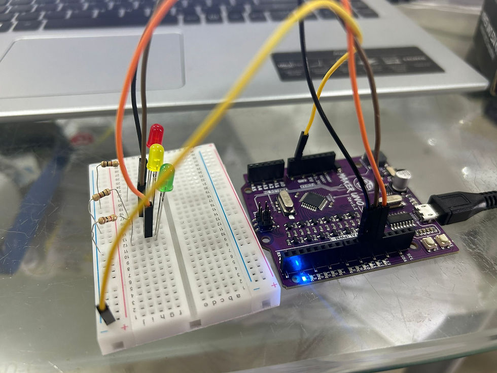
Compared to the setup shown in video, it is much simpler yet functionable.
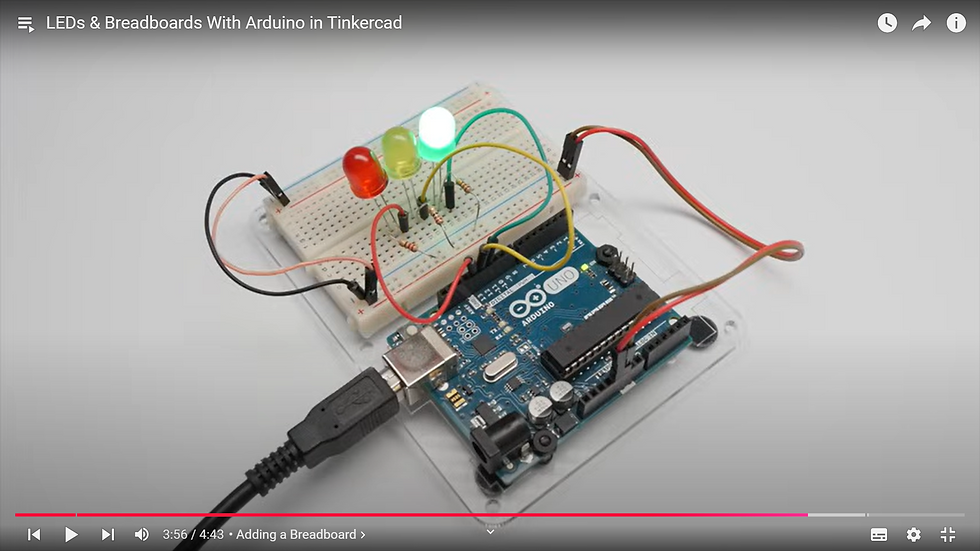
After the challenge is overcame, let us do the coding part for different ways to flash the LEDs.
Fade and flash 3 LEDs sequentially.
This is the setup that I have come up with in Tinkercad and the FOREVER block code is being modified into ON START to flash the LEDs when button is on.
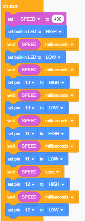
Change the block code into text to get the Arduino code to try out on the Maker-Uno board on Arduino IDE!
This is the code to flash the LEDs sequentially.
int SPEED = 0;
const int buttonPin = 2;  // Pin where the button is connected

void setup() {
  pinMode(LED_BUILTIN, OUTPUT);
  pinMode(10, OUTPUT);
  pinMode(11, OUTPUT);
  pinMode(12, OUTPUT);
  pinMode(buttonPin, INPUT_PULLUP);  // Set button as input with pull-up resistor
}

void loop() {
  int buttonState = digitalRead(buttonPin);

  if (buttonState == LOW) {  // Check if button is pressed (LOW due to pull-up)
    SPEED = 400;

    digitalWrite(LED_BUILTIN, HIGH);
    delay(SPEED);
    digitalWrite(LED_BUILTIN, LOW);
    delay(SPEED);

    digitalWrite(10, HIGH);
    delay(SPEED);
    digitalWrite(10, LOW);
    delay(SPEED);

    digitalWrite(11, HIGH);
    delay(SPEED);
    digitalWrite(11, LOW);
    delay(SPEED);

    digitalWrite(12, HIGH);
    delay(SPEED);
    digitalWrite(12, LOW);
  }
}This is the first code that I have produced to blink the 3 lights in sequence when button is pressed.
Fade and flash 3 LEDs simultaneously.
Below is the modified code and video evidence to flash 3 LEDs at the same time when button is pressed.
int SPEED = 0;
const int buttonPin = 2;  // Pin where the button is connected

void setup() {
  pinMode(LED_BUILTIN, OUTPUT);
  pinMode(10, OUTPUT);
  pinMode(11, OUTPUT);
  pinMode(12, OUTPUT);
  pinMode(buttonPin, INPUT_PULLUP);  // Set button as input with pull-up resistor
}

void loop() {
  int buttonState = digitalRead(buttonPin);

  if (buttonState == LOW) {  // Check if button is pressed (LOW due to pull-up)
    SPEED = 400;

    // Turn all LEDs ON
    digitalWrite(LED_BUILTIN, HIGH);
    digitalWrite(10, HIGH);
    digitalWrite(11, HIGH);
    digitalWrite(12, HIGH);
    delay(SPEED);

    // Turn all LEDs OFF
    digitalWrite(LED_BUILTIN, LOW);
    digitalWrite(10, LOW);
    digitalWrite(11, LOW);
    digitalWrite(12, LOW);
    delay(SPEED);
  }
}
Fade 1 of the LEDs and flash the other 2 simultaneously
To account for every possibility of combinations,
1. When button pressed the first time, red and yellow on.
2. When button pressed the second time, red and green on.
3. When button pressed the third time, yellow and green on.
Below is the code for this action.
const int buttonPin = 2;  // Button pin
const int redLED = 10;    // Red LED pin
const int yellowLED = 11; // Yellow LED pin
const int greenLED = 12;  // Green LED pin

int flashLED1 = redLED;   // First flashing LED
int flashLED2 = yellowLED; // Second flashing LED
int offLED = greenLED;    // Initially OFF LED

bool buttonPressed = false;  // Track button state
int SPEED = 400;             // Flash speed

void setup() {
  pinMode(buttonPin, INPUT_PULLUP); // Set button with pull-up resistor
  pinMode(redLED, OUTPUT);
  pinMode(yellowLED, OUTPUT);
  pinMode(greenLED, OUTPUT);
}

void loop() {
  // Check for button press
  if (digitalRead(buttonPin) == LOW && !buttonPressed) {
    buttonPressed = true;  // Mark button as pressed

    // Cycle through LED combinations
    if (flashLED1 == redLED && flashLED2 == yellowLED) {
      flashLED1 = redLED; flashLED2 = greenLED; offLED = yellowLED; // Next: Red + Green flash
    } else if (flashLED1 == redLED && flashLED2 == greenLED) {
      flashLED1 = yellowLED; flashLED2 = greenLED; offLED = redLED; // Next: Yellow + Green flash
    } else {
      flashLED1 = redLED; flashLED2 = yellowLED; offLED = greenLED; // Reset: Red + Yellow flash
    }

    delay(200); // Debounce delay
  } else if (digitalRead(buttonPin) == HIGH) {
    buttonPressed = false; // Reset button state
  }

  // Flash the two active LEDs
  digitalWrite(flashLED1, HIGH);
  digitalWrite(flashLED2, HIGH);
  digitalWrite(offLED, LOW);  // Ensure the OFF LED is OFF
  delay(SPEED);

  digitalWrite(flashLED1, LOW);
  digitalWrite(flashLED2, LOW);
  delay(SPEED);
}
And this is the video evidence of the code running on Arduino board.
Reflection on Practical 2
For pre-practical, we are tasked to complete 4 challenges to gain a foundational understanding on Arduino programming on its motherboard which are:
Change LED bulletin and speed.
Programmable button.
Make some melody.
Servo motor turning speed and angle.
With these experiences, I am able to understand and modify the code produced by ChatGPT for our in class practical. Still remember the shark that made in my blog last semester? Now for in class activity we are tasked to perform the shark's main function, which we decided to open and close its jaw and add on additional function.
Therefore, we added baby shark song, which align with the theme of model that we built, and use programmable button to control on and off the loop of melody and servo motor.
Some reflection/conclusion for preparation of code before in class practical,
ChatGPT sucks at music theory
It will not give you the correct notes and rhythm if you ask it to produce any song other than Twinkle Twinkle Little Star
Every problems need a solution, if AI can't help, use human brain. 🤯 To understand the code, breaking it down is necessary.
a. Notes of melody
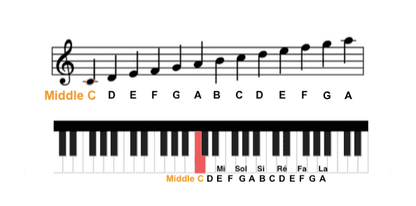
WHAT, getting notes in alphabet and number? It's actually from the American system for notating pitches, called Scientific Pitch Notation (SPN). This sounds complicated, but in reality it's really simple! All it takes is a basic knowledge of the piano keyboard.
To modify the code on your own, the letter means the name of the pitch and number is the octave of the pitch. For example, C4 means the middle C on piano keyboard. To make things simple, the name of notes will only consist CDEFGAB these 7 letters, which stands for Do Re Mi Fa So La Ti respectively that we are familiar with. After letter B, it will repeat to C which is one octave higher than the previous C note. Moving number 4 to 5 will move the notes one octave up which will increase the frequency of the sound so on and so forth.
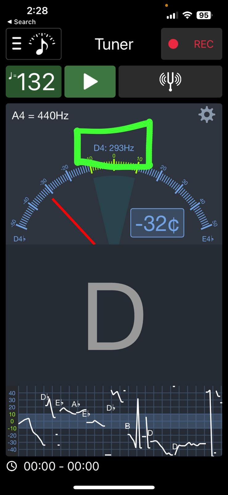
Still unable to find the notes? Honestly, although I have been learning the violin since kindergarten age, I do not have PERFECT PITCH as well. Therefore, online app can help to identify the notes too! Just download any tuner which musicians use for tuning their instruments and use your voice to sing along the song that you want to generate the code!
Fun fact time:
1. Middle C is called middle C is not because of it is the middle key on 88th piano key. In fact, it is the center point between treble clefs (generally used for higher-pitched instrument like violin or voice like soprano) and bass clefs (generally used for lower pitched instrument like cello or voice like bass)
2. Why there is no H in notes? The seven-note structure of Western scales is adopted from the historical development. This is due to the reason that the 8th note will have the same pitch as the first but higher in frequency, there is no need to add more complicating letters.
b. Duration of melody
After understanding how to modify the note of melody, we will now be learning how to adjust the duration of each note.
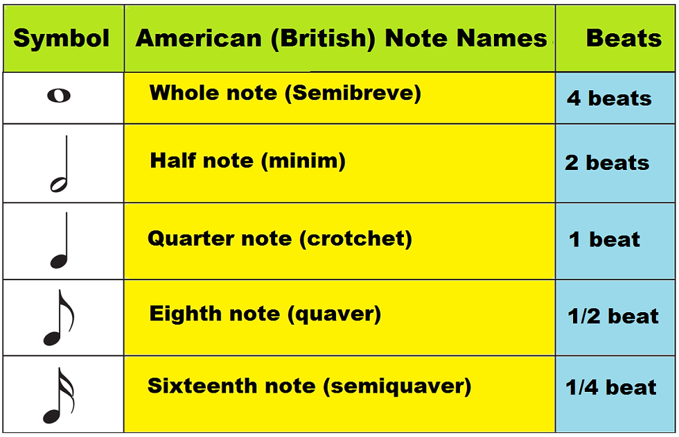
Basically if you want the rhythm to be faster, just lower down the number and vice versa.
I have covered the core part of ChatGPT unable to provide. Other than that, to adjust the speed of the song or the completeness of playing the full song after modifying the notes and duration, can just use ChatGPT.
Time for some hands-on practice for any songs: trending APT on Arduino!
Need to train ChatGPT with countless instruction with clear and repeated explanation to reach to the combination of code that works for the desired outcome.
After multiple tries in class of giving the right instruction to ChatGPT to produce the output that we want, below is the code that we used for combining the servo + melody simultaneously with programmable button 3 in 1 function. Do not forget to include the library that required in functioning i.e. pitches, servo.
#include <Servo.h>
#include "pitches.h"

// Pin definitions
const int buttonPin = 2;    // Button connected to digital pin 2
const int speakerPin = 8;   // Speaker connected to digital pin 8
const int servoPin = 9;     // Servo connected to digital pin 9

// Servo setup
Servo myServo;               // Create a Servo object
int servoAngle = 0;          // Current servo angle
unsigned long previousMillis = 0;
const unsigned long servoMoveInterval = 200; // Interval to move the servo (milliseconds)

// Melody and note durations
int melody[] = {
  NOTE_C4, NOTE_D4, NOTE_F4, NOTE_F4, NOTE_F4, NOTE_F4, NOTE_F4, NOTE_F4,   // "Baby shark, doo doo doo"
  NOTE_C4, NOTE_D4, NOTE_F4, NOTE_F4, NOTE_F4, NOTE_F4, NOTE_F4, NOTE_F4,   // "Baby shark, doo doo doo"
  NOTE_C4, NOTE_D4, NOTE_F4, NOTE_F4, NOTE_F4, NOTE_F4, NOTE_F4, NOTE_F4,   // "Baby shark, doo doo doo"
  NOTE_F4, NOTE_F4, NOTE_E4                                                // "Baby shark"
};

int noteDurations[] = {
  2, 2, 4, 4, 4, 8, 4, 4,
  4, 4, 4, 4, 4, 8, 4, 4,
  4, 4, 4, 4, 4, 8, 4, 4,
  4, 4, 4
};

// Variables
bool isPlaying = false;      // Tracks if the melody is playing
bool lastButtonState = LOW;  // Tracks the previous state of the button

void setup() {
  pinMode(buttonPin, INPUT_PULLUP); // Set button pin as input with pull-up resistor
  pinMode(speakerPin, OUTPUT);     // Set speaker pin as output
  myServo.attach(servoPin);        // Attach the servo to pin 9
  myServo.write(servoAngle);       // Set initial servo position
}

void loop() {
  // Read the button state
  bool currentButtonState = digitalRead(buttonPin);

  // Detect button press (toggle state on button press)
  if (currentButtonState == LOW && lastButtonState == HIGH) {
    isPlaying = !isPlaying; // Toggle the play state
    delay(200);             // Debounce delay
  }
  lastButtonState = currentButtonState;

  // Play melody and move servo if isPlaying is true
  if (isPlaying) {
    for (int thisNote = 0; thisNote < 27; thisNote++) {
      // Check if the button was pressed again to stop
      currentButtonState = digitalRead(buttonPin);
      if (currentButtonState == LOW && lastButtonState == HIGH) {
        isPlaying = false; // Stop playing
        delay(200);        // Debounce delay
        break;
      }
      lastButtonState = currentButtonState;

      // Servo movement logic
      unsigned long currentMillis = millis();
      if (currentMillis - previousMillis >= servoMoveInterval) {
        previousMillis = currentMillis;

        // Toggle between 0° and 90°
        servoAngle = (servoAngle == 0) ? 90 : 0;
        myServo.write(servoAngle);
      }

      // Play the current note
      int noteDuration = 1000 / noteDurations[thisNote];
      tone(speakerPin, melody[thisNote], noteDuration);

      // Pause between notes
      int pauseBetweenNotes = noteDuration * 1.30;
      delay(pauseBetweenNotes);
      noTone(speakerPin);
    }
  }
}
This is the final product that my group have made. Sorry technical issue so only shark head is available. NGL it really looks like curry fish head, imagine I am writing this blog at 230am (sleeping schedule is cooked) ...lowkey want to get supper now.

Rate our shark!!!🦈🦈🦈
😭Bad
😑So so
😁 Amazing
During the lesson, an additional feature was required: a mechanical mechanism to support the jaw-opening function. We initially decided to use a seesaw mechanism, where the movement of the servo motor would push one stick down, which in turn would lift another stick to open the shark's jaw. However, we were distracted by the lecturer's suggestion to make adjustment on the mechanism which led to a significant amount of time being wasted and ultimately slowed down our progress.
What we learned from this experience is the importance of being firm and confident in the ideas we choose to pursue. Instead of overthinking or constantly redoing components, we should have moved forward with the initial concept, as it was functional and aligned with the task. This would have allowed us to proceed more efficiently and make the necessary adjustments later if needed.
As a result of the delays, we ran out of time to focus on the aesthetic aspects of the project. The model base ended up was simply made from cardboard that was not cut neatly to the required size. This lack of attention to the finishing touches made the final product look incomplete and visually unappealing, as everything was just placed on top without a proper, aesthetically pleasing structure.
Moving forward, we’ve learned that it’s crucial to balance functionality with appearance for final presentation. Being decisive and staying on track with the project will help ensure that all aspects of the build, both technical and visual, are well-executed.
Overall Reflection on Learning Arduino
In this practical session, I learned essential technical skills, including how to connect the right setup of the accessories to an Arduino board and make the code successfully perform its command on the board. Additionally, I developed a better understanding of how to interpret and adapt online resources, which deepened my grasp of the code’s functionality and how it translates into tangible outputs.
This journey taught me the importance of curiosity and perseverance. Learning is not a linear path, it often involves trial and error. As the famous inventor Thomas Edison once said: "I have not failed. I've just found 10,000 ways that won't work."
Every mistake is a steppingstone toward mastery. Although making errors can be frustrating, the experiences refined our skills and strengthened our knowledge. The willingness to embrace challenges, no matter how daunting, is crucial because nobody is born to be an expert. Every great innovator, engineer, or creator started with uncertainty and built their expertise through dedication and hard work. We should never fear challenges or failures as they are the foundation of personal and professional growth. With persistence, the hard work invested will eventually bear fruit in the form of confidence and technical competence.
Although the knowledges that we learn in this module are new and often require self-directed learning, always be focus and explore with an open mind. You will find the learning process challenging yet ultimately rewarding. "Life stop when you stop exploring", a meaningful quote by one of my favourite Youtube content creator Torres Pit.
Tqqq for spending your precious time reading this lengthy blog 🤓
*Finally finish rushing the blog before MST🎃. Just don't want to leave anymore schoolwork for holiday and it is time for my exciting first overseas solo trip before my last teen year ends! Time flies, turning 20 soon...
See you again when I come back to school for blog 3!
Comments